LH Zenette Ch= 2022
Zenith Radio Corp.; Chicago, IL
- Land
- USA
- Hersteller / Marke
- Zenith Radio Corp.; Chicago, IL
- Jahr
- 1931/1932
- Kategorie
- Rundfunkempfänger (Radio - oder Tuner nach WW2)
- Radiomuseum.org ID
- 18990
-
- anderer Name: Chicago Radio Lab


Export Mod. 220 Volt


Klicken Sie auf den Schaltplanausschnitt, um diesen kostenlos als Dokument anzufordern.
- Anzahl Röhren
- 7
- Hauptprinzip
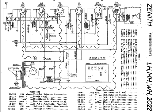
- Super mit HF-Vorstufe; ZF/IF 175 kHz
- Anzahl Kreise
- 7 Kreis(e) AM
- Wellenbereiche
- Mittelwelle, keine anderen.
- Betriebsart / Volt
- Wechselstromspeisung / 115 Volt
- Lautsprecher
- Dynamischer LS, mit Erregerspule (elektrodynamisch)
- Material
- Gerät mit Holzgehäuse
- von Radiomuseum.org
- Modell: LH Zenette Ch= 2022 - Zenith Radio Corp.; Chicago,
- Form
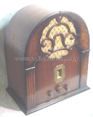
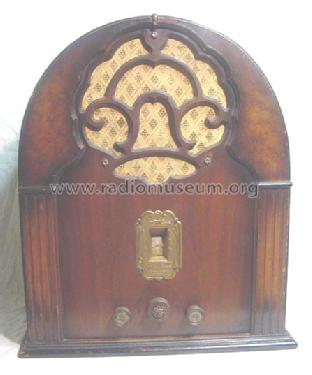
- Tischgerät, Kathedralenform (Hochformat, bogig bis spitzbogig, nicht nur runde Ecken).
- Bemerkung
- [3331454B] This model LH Zenette with chassis 2022 has an unusual 4-gang variable condenser but only 3 IF cirquits - in total 7 tuned circuits. There are also export models with other mans transformers.
- Originalpreis
- 50.00 $
- Datenherkunft extern
- E. Erb 3-907007-36-0
- Datenherkunft
- Zenith Radio The Early Years 1919-1935
- Schaltungsnachweis
- Rider's Perpetual, Volume 2 = 1932 (Models 1931/1932)
- Literaturnachweis
- Radio Collector`s Guide 1921-1932
- Literatur/Schema (1)
- Thali schematics, Switzerland Zenith page 5
- Weitere Modelle
-
Hier finden Sie 4519 Modelle, davon 4111 mit Bildern und 3656 mit Schaltbildern.
Alle gelisteten Radios usw. von Zenith Radio Corp.; Chicago, IL
Sammlungen
Das Modell LH Zenette befindet sich in den Sammlungen folgender Mitglieder.
Forumsbeiträge zum Modell: Zenith Radio Corp.;: LH Zenette Ch= 2022
Threads: 1 | Posts: 1
Repair of the Zenette LH transformer.
In my opinion the voltage change from 110 to 220 V, many years ago, seemed the end of life for this radio. To prevent such a mistake a second time I constructed the new transformer ready for the 235 V mains.
The pictures below nearly tell the whole story. The high voltage secondary was damaged by a short circuit. Counting the windings at disassembly shows 4 turns/volt. For comfort two flanges were added.
The transformer was rebuilt as follows:
§ High voltage secondary 2760 turns with center tab, dia 0.15 mm (2 x 345 V)
§ Paper
§ Copper screen from the original transformer. Electrical tape is used to prevent the copper foil to act as a short circuit winding.
§ Paper
§ Primary 940 turns, dia 0.35 mm (235 V)
§ Paper
§ 5 volt secondary, 20 turns, dia 1.1 mm
§ Electrical tape for insulation and to fix the wire.
§ 2.5 volt secondary, 10 turns with center tab, 2.5 mm2 multicore wire. The center tab is connected with a 0.5 mm2 wire.
§ Electrical tape
All wire is renewed. Backing paper was used for separation between all layers. The width of the paper is a bit larger than the inner distance between the flanges to ensure good insulation at the outside. Because the original thick 2.5 volt wire was in bad condition I replaced it with 2.5 mm2 multicore wire. This wire has the advantage being very flexible. Winding is done with a 12V-drilling machine. A foot switch applies the 12V power.


Eduard Hontele, 07.May.08