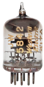
5842
|
|
|||||||||||||||||||||||||||||||||||
|
Klicks: 13612 Antworten: 8
5842-417A Highest gm
|
|
|
Joe Sousa
27.Mar.09 |
1
Radio Age magazine editor Ed Lyon has asked me if I have ever seen a small-signal VHF/UHF receiving tube with more transconductance than the 5823/417B. At one point in his career he used these tubes as cathode followers to drive coaxial cables. The 417B designation is for Western Electric, and 5823 is US military. The 5823 has a specified transconductance between 19mS and 29mS, for the Philips version. The Raytheon version specifies 25mS at 150V, 25mA. mu=43 1mS/mA at 150V is not rare. The 12AX7 does that, but the size efficiency of the 5823 is much greater than the 12AX7. This is extraordinarily high gm for a very small VHF tube. VHF receiving tubes in this class have gm no higher than 15mS. The plate length of the 5823/417A is approximatelly one third of the length of the plate of the 12AX7, yet it has 25x more gm and current at comparable plate voltages. The small size means that the capacitances will be modest (cga1.8pF, cgk=9pF) and make it possible to realize very high gm/C bandwidth. With an infinite load impedance the internal impedance of 43/25mS=1.7KOhms and the plate capacitance of 1.8pF gives a 500MHz bandwidth with a grounded grid stage, if parasitic inductance and capacitance effects could be controled. Perhaps there are triodes with a faster transit time, but transit time is not specified. Are there receiving triodes with a higher gm/C bandwidth? Is there a higher performing UHF pencil or ceramic receiving tube? The plate size in combination with the high gm of the 5823 also suggest extermelly small internal grid-cathode spacing. I expect that these questions can be answered in different ways, depending on what parameters are taken as most important. Best regards, -Joe |
|
Emilio Ciardiello
27.Mar.09 |
2
Your question involves many considerations, also including the internal geometry of the tube and the external circuitry. I can only add a little information about high gm planar tubes. Regards, Emilio |
|
Joe Sousa
02.Apr.09 |
3
Thank you very much for the response. I just got a few minutes to respond. Did the 5842 have a wire ladder grid, or a planar mesh grid? Was it the fastest tube with a wire grid? You mention STC. I presume you mean STC/Brimar English tube maker. I took your leads on planar tubes, and found that I have a few in my collection that have gm up to 50mS. All of these are Cermet or other variants, with opaque construction. A few examples: D3A=7721 minuature glass RF pentode has 40mS and extensivelly specified at 100MHz. Pictures suggest wire grid construction. A cermet 7588 with 45mS mu=175 for 500MHz RF amp service:
A metal/glass-seal 416B by Western Electric has 50mS mu=300 and 4GHz operating frequency. I own a couple of these. I hope to take a picture soon. Best regards, -Joe |
|
Emilio Ciardiello
02.Apr.09 |
4
Dear Joe, Anlagen
|
|
Joe Sousa
03.Apr.09 |
5
Dear Emilio, Thank you for the comprehensive answer. My curiosity exceeded my ability to ask good questions, however, your exposition gives a very clear outline of the history of these tubes. The illustrations are great too. One very important clarification was the meaning of "planar". It refers to the flatened elements, arranged in a parallel fashion. This contrasts with older cylindrical concentric designs. Another clarification is the meaning of "frame" grid. The frame grid has it's wires wrapped around a rectangular frame for good control of tension, as opposed to being wrapped around two posts supported by mica discs, like a ladder. Another type of tube structure that is unique to Russian subminiature tubes is a structure made entirely of parallel rods. One example is the 1J17B subminiature. The cathode is a single filament, the control grid is two flattened rods on either side of the filamentary cathode, the screen grid is made with two pairs of additional rods, more rods for the suppressor, and finally two anode rods in diametric opposition to catche the two opposing sheet beams emanating from the filamentary cathode. They have about 1mS of transconductance, but much faster transition times that the equivalent western 5678. I measured 1.8ns delay for a 2V step delay through the 1J17B, and 3ns delay through a 5678. Sub-ns rise and fall times for the 1J17B were sharper than the faster delay time might suggest. I have not seen a Western filamentary tube that could match the performance of the Russian rod tubes. I was also surprised to hear that ladder grids, as opposed to mesh grids, were very common with these tubes. And the 8micron thick ladder grid was spaced only 15microns from the Cathode. Pretty amazing. ( I am using microns=0.001mm because I work with microns in my IC design work. I think this is the first time I ever referred to tubes and transistors in the same dimensional scale.) This evening I got a chance to photgraph 3 planar tubes. The top one is a 5675 pencil, the Western Electric 416B is to the lower right, and a 7820 nuvistor-like tube completes the set. I have not been able to find any info on the 7820. Best regards, -Joe |
|
Emilio Ciardiello
03.Apr.09 |
6
Dear Joe,
Anlagen |
|
Joe Sousa
04.Apr.09 |
7
Dear Emilio, thank you again for further expanding my understanding of VHF/UHF tubes. Your modesty claiming that you don't know very much about these tubes, indicates to me that you know that there is much more to know about these tubes. Your knowledge, however, is quite impressive! Recently, I wrote an article about Russian subminiature filamentary battery Pentodes with rods used for all the grids and anode. Ludwell Sibley is currently editing my article for publication in the Tube Collector's Association newsletter. In the article I share voltage sweep curves showing impressive voltage gain linearity and also faster step response than comparable western subminiature battery tubes. The pictures you posted of various grid structures show structures that I had not seen. I was already familiar with sqirrel cage grids in transmitting tubes, but the use of individual rods for all the tube elements is quite unique, and has unique benefits. The following photo shows some detail of 1J29B filamentary Russian Subminiature Pentode that I sacrificed to remove the glass. The following photo shows the rod arrangement to implement G1, G2, G3, Anode, and shield rods S. The filament is represented by the two smallest white dots at the center and consists of two segments wire beyond the micas to the rods labeled F1-F3. The dashed lines represent electron flow. These tubes were used exclusively in Russian Military radios. The original Russian data sheet indicates that these tubes were intended for 60MHz service, however my step response measurements indicate that their 1.8ns delay time will provide useful service into the VHF range. Aside from the very good gain linearity and very fast transit time of these tubes, they perform similarly in power and gain to the 5678 and their brethren. Your comments about the importance of cathode emission for fast pulse response help me understand the sub-ns rise time I was seeing after the 1.8ns delay in the 2V step response of the 1J17B. The filamentary cathode is a thin capilary, so electrons leave the cathode synchronously when G1 steps from -2V to 0V. This is also the case with a planar tube with very flat cathode and grid construction and very good parallel allignment. The parallel G1 rod alignment also favors a more direct control of electron flow because there are no grid wires in the way for the electrons to move around, and no problems of "inselbildung" that dispose the electron cloud at various distances from the grid. Another characteristic worthy of note in the step response was the very well matched rise and fall delays and the very well matched rise and fall times in the 1J17B step response. Most other VHF unipotental cathode tubes I tested (6HQ5, 6HA5, 6EV5, 6EA5, among others) showed noticeable assimmetry in the rise and fall times of their step response, with the turn-on response to a rising grid step being slower. This is to be expected from the cylindrical shape of the cathode, with electrons departing the cathode at various distances from the grid. This further illustrates the speed benefit of planar structures. I just made a quick calculated estimate of the current density at the surface of the 1J17B cathode, and came up with 150mA/cm2; very much in line with the receiving tube density you mention above. I estimated the filament at 0.025mm thickness from a close up photo, and multiplied the circumference by 25mm length. I used 3mA for the current, which is what flows with zero G1 bias and 45V at G2 and Anode. I have a lot more material in the article about the Russian subminiature rod tubes, but this discussion has advanced my understanding of how these tubes work with regard to the importance of the filamentary cathode and rod control grid. Amazing to hear about 30A/cm2 in high power pulsed transmitting tubes. This is also the first time I have ever heard of a 1S (mho) tube. Was this a monster transmitting tube several feet long, or somthing not much bigger than a fist? I knew about the TEK519, but had not looked closely into it's circuitry. I found the 4CX250F 2ns/div generator tube on page 98 of the DJVU file available at BAMA. http://bama.edebris.com/manuals/tek/519/ Surprising to see the 4CX250F followed by 6DJ8 follower a 6DJ8 bootstrap and another 6DJ8 driving the 100 Ohm deflecton plates. Which of my planar tubes do you suggest I measure for step response? Would the WE416B be a good choice? I own three of these. I also own two of the pencil types. It would be trully amazing if the 200mW 1J17B was comparable in step response to tubes dissipating more than 10X more power. Best regards, -Joe |
|
Emilio Ciardiello
05.Apr.09 |
8
Dear Joe, |
|
Joe Sousa
21.Sep.09 |
9
Hello Emilio, I have a new post with updated internal dimensions of the Russian Subminiature Tubes. I just noticed that I never got around to measuring step response of the UHF planar tubes, as you suggested. Perhaps I will find some time soon. Regards, -Joe |
Ende Forumsbeiträge zur Röhre
| Datenkonformität | Mehr Informationen |

