
CV73

|
|
||||||||||||||||||||||||||||||||||||||||||||

|
Klicks: 3937 Antworten: 3
CV73 (CV73)
|
|||||||||||||||||||||||||||||||||||||
|
David Phillips
19.Jun.09 |
1
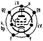
Note the CV73 has a sister tube. It is a very similar tube with a similar name: CV72. Some CV72s may be slightly shorter but otherwise it appears identical, having a B7 base also. The number-difference on the labels can be easily overlooked because they look so similar and tend to be found in a group together. The pinout is ALMOST identical, except for one difference which means neither tube will work if interchanged: the g2 electrode pin-connections are different, (usually causing the screen to be low) with the result that the tube appears to have no emissions. The close resemblance and apparent no-emission results has nearly caused me to junk a very good CV72 tube. There is a good picture at http://www.tubecollector.org/cv72.htm . (NoteI have one example of this valve which behaves as if it has a 4-volt heater (reaches full current at 4.6 Volts, not 6.3 as per the spec). |
||||||||||||||||||||||||||||||||||||
|
Jacob Roschy
20.Jun.09 |
2
Hello David, thank you for this information. But I still feel confused about the swapped g2 and g3 electrode pin-connections, as the base diagrams always shows g3 connected to cathode internally. Are probably g2 and g1 swapped ? So can you please check the base diagrams of both tubes and post the correct ones to here ? Thanks in advance, Jacob |
||||||||||||||||||||||||||||||||||||
|
David Phillips
20.Jun.09 |
3
Thanks Jacob - I have checked this: it is only the screen grid that moves (as you say the beam forming plates and internally connected to the cathode in both tubes). The screen (g2) is on pin 7 for the CV73, but for CV72 it is on pin 3 (with pin 7 n/c). Pin 3 should be left n/c for CV73). The control grid (g1) remains on pin 2 for both tubes The full base diagrams are below. (I also added information about heater behaviour). Thanks,
|
||||||||||||||||||||||||||||||||||||
|
Jacob Roschy
05.Jul.09 |
4
Hello David, now I have designed a new base diagram for the CV72 corresponding to your informations. Now how are the base diagrams for the similar types V1120B and 11E3 ? Regards, Jacob
|
||||||||||||||||||||||||||||||||||||
Ende Forumsbeiträge zur Röhre
| Datenkonformität | Mehr Informationen |