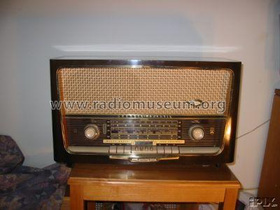
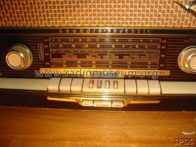
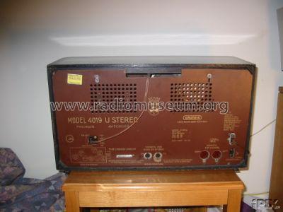
Majestic 4019 U Stereo
Grundig (Radio-Vertrieb, RVF, Radiowerke); Fürth/Bayern
- Country
- Germany
- Manufacturer / Brand
- Grundig (Radio-Vertrieb, RVF, Radiowerke); Fürth/Bayern
- Year
- 1959/1960
- Category
- Broadcast Receiver - or past WW2 Tuner
- Radiomuseum.org ID
- 90975
-
- alternative name: Grundig Portugal || Grundig USA / Lextronix
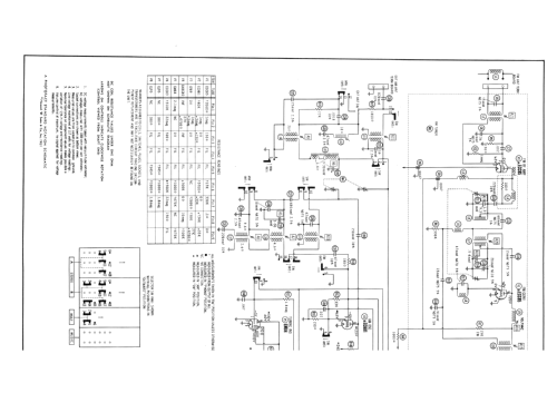
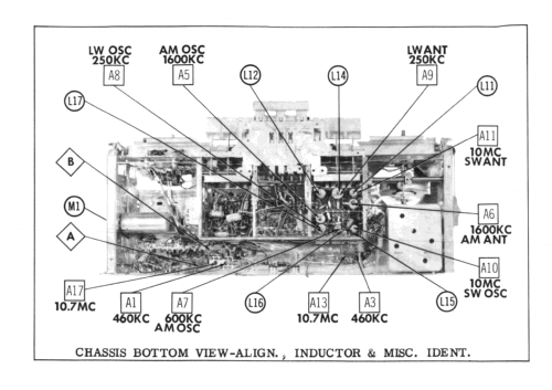
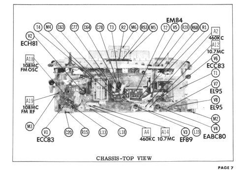
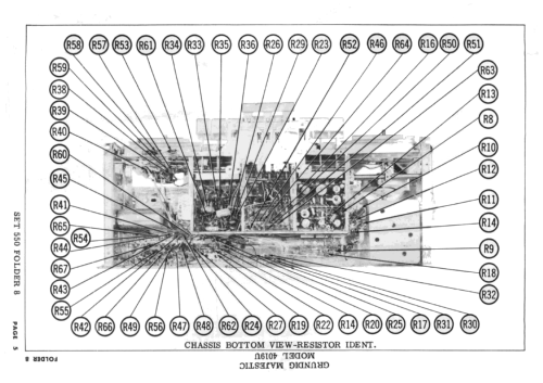
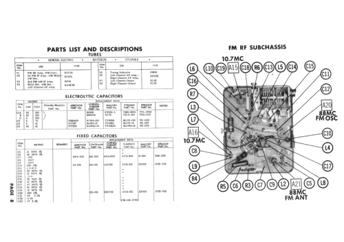
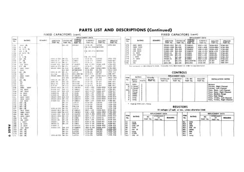
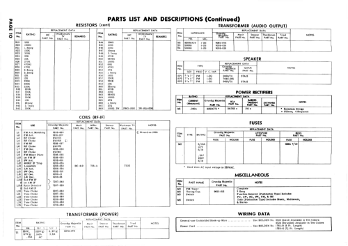

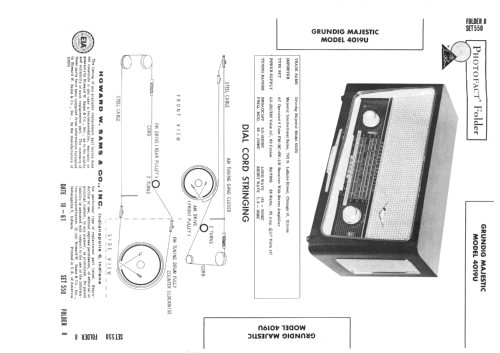
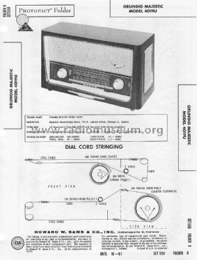
Sams PhotoFact Folder 8, Set 550, DAte 10-61
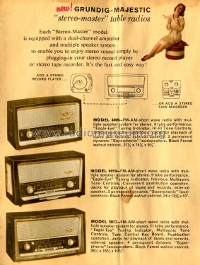
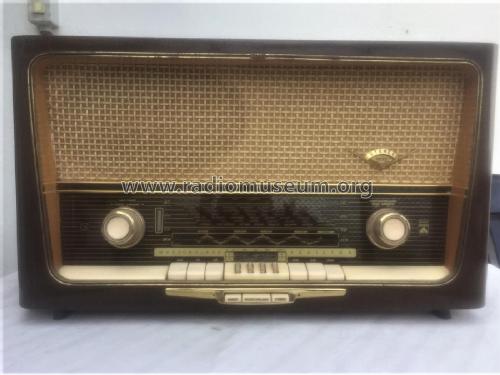
Picture from Grundig Majestic Brochure
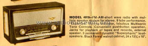
Picture from Grundig Majestic Brochure
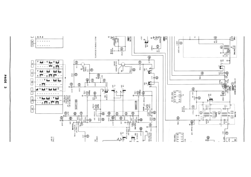
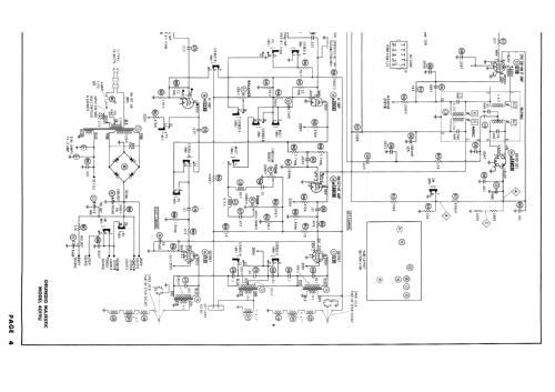
Click on the schematic thumbnail to request the schematic as a free document.
- Number of Tubes
- 8
- Number of Transistors
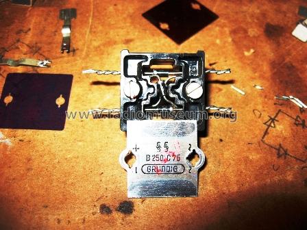
- Semiconductors
- B250C75
- Main principle
- Superheterodyne (common); ZF/IF 460/10700 kHz
- Tuned circuits
- 6 AM circuit(s) 10 FM circuit(s)
- Wave bands
- Broadcast, Long Wave, Short Wave plus FM or UHF.
- Power type and voltage
- Alternating Current supply (AC) / 110-120; 220 Volt
- Loudspeaker
- 3 Loudspeakers
- Material
- Wooden case
- from Radiomuseum.org
- Model: Majestic 4019 U Stereo - Grundig Radio-Vertrieb, RVF,
- Shape
- Tablemodel with Push Buttons.
- Dimensions (WHD)
- 610 x 350 x 250 mm / 24 x 13.8 x 9.8 inch
- Notes
-
UKW 88 - 108MHz.
This is the export version of Grundig Konzertgerät 4019 Stereo.
- Literature/Schematics (1)
- -- Original-techn. papers.
- Author
- Model page created by Ernst Erb. See "Data change" for further contributors.
- Other Models
-
Here you find 6250 models, 5496 with images and 4249 with schematics for wireless sets etc. In French: TSF for Télégraphie sans fil.
All listed radios etc. from Grundig (Radio-Vertrieb, RVF, Radiowerke); Fürth/Bayern
Collections
The model Majestic is part of the collections of the following members.
Forum contributions about this model: Grundig Radio-: Majestic 4019 U Stereo
Threads: 3 | Posts: 11
I have a 4019U that plays very well, but the stereo balance control does not work. After checking all the switch contacts, tubes, capacitors, most of the resistors .Not being familiar with this model, I need some help getting this radio to work properlly.Would someone please help me? Thank you Ross W. Hoff
Ross Hoff, 08.Feb.19
- C58 and C59 values swapped on the Sam's.
- T4 secondary wire colors swapped. Green is ground and puts speaker SP3 electrically out of phase with SP1. The input to V8 is 180 degrees out of phase with V7.
- Page 7, A4 and A14 swapped.
- Page 7, V1 is not ECC83 (12ax7) but is an ECC85 (6AQ8).
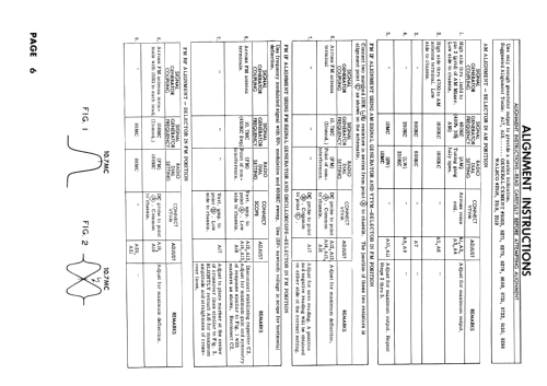
- Page 6 step 6, there is no A15 FM IF adjustment.
- Page 6 step 7, A17 will not to to Zero. Refer to 4019 domestic unit procedure www Radiomuseum.org to confirm that A17 is to be adjusted to Minimum voltage.
- Various capacitors are miss labeled and not identified on page 2.
Happy Restorations,
Paul.
Paul E. Pinyot † 2013, 08.Mar.11
When I first played this radio after the chassis restoration, there was a horrible bass rattle in the oval speaker. When I pulled it for inspection I found all the foam gasket had deteriorated along with the voice coil dust cover.

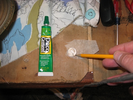


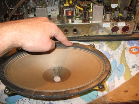
Paul E. Pinyot † 2013, 03.Mar.11