Tube Tester TV-7 U
MILITARY U.S. (different makers for same model)
- Pays
- Etats-Unis
- Fabricant / Marque
- MILITARY U.S. (different makers for same model)
- Année
- 1953 ?
- Catégorie
- Appareils de mesure et de dépannage (matériel de labo)
- Radiomuseum.org ID
- 68935
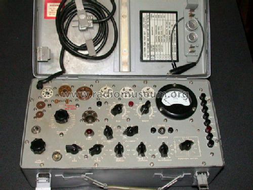
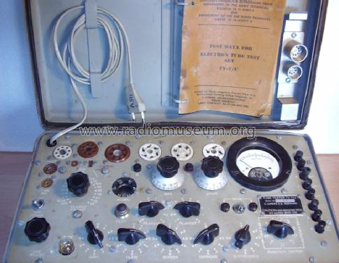
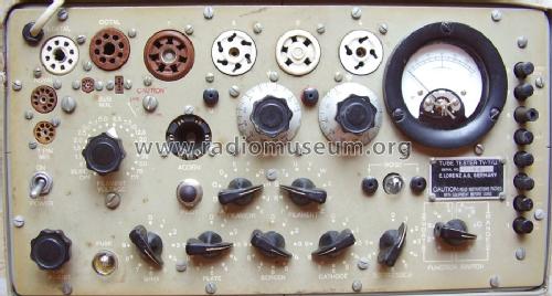
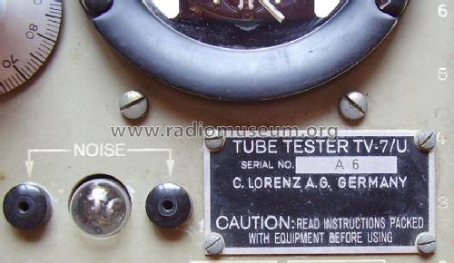
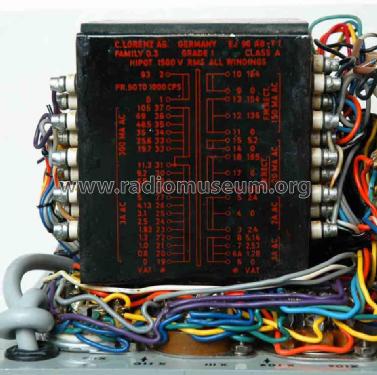
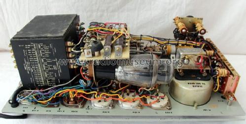
This TV-7/U was build in Germany by Lorenz
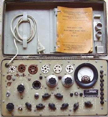
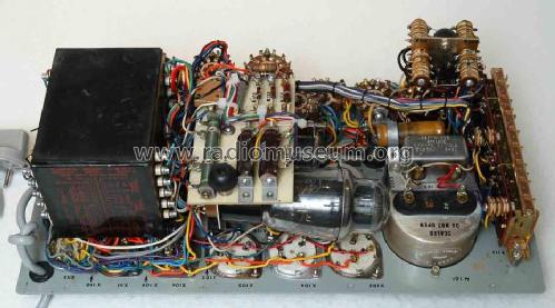
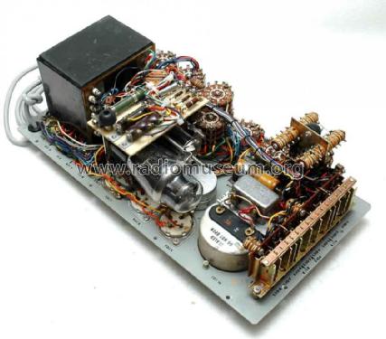
From eBay France N°:331165593414
From eBay France N°:331165593414
From eBay France N°:331165593414
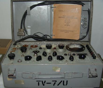
From eBay France N°:331168578026
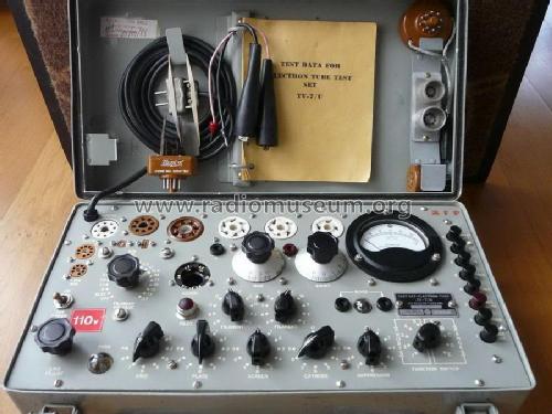
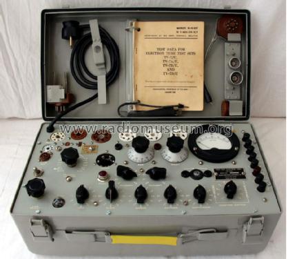
TV7/U état de marche,Armée Française
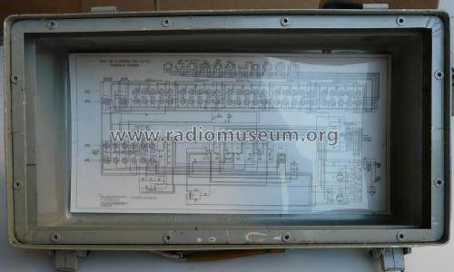
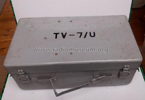
Coffret avec schéma
Cliquez sur la vignette du schéma pour le demander en tant que document gratuit.
- No. de tubes
- 2
- Gammes d'ondes
- - sans
- Tension / type courant
- Alimentation Courant Alternatif (CA) / 105-125 Volt
- Matière
- Boitier métallique
- De Radiomuseum.org
- Modèle: Tube Tester TV-7 U - MILITARY U.S. different makers
- Forme
- Modèle de table générique
- Dimensions (LHP)
- 440 x 220 x 155 mm / 17.3 x 8.7 x 6.1 inch
- Remarques
-
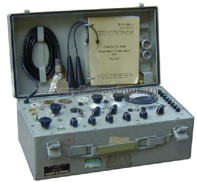
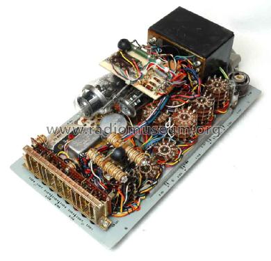
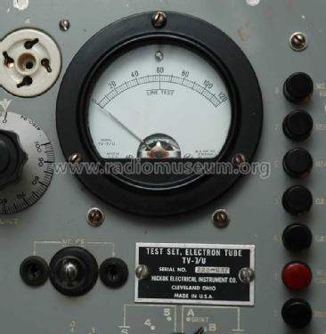
Tube Tester TV-7 /U.
This model /U was built by Supreme.
This model was also produced for NATO by Lorenz, Germany.
- Source extérieure
- Ralf Sürtenich
- Schémathèque (4)
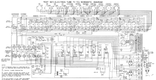
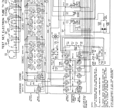
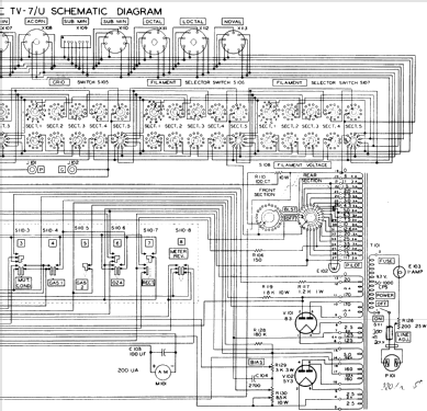
- -- Schematic
- D'autres Modèles
-
Vous pourrez trouver sous ce lien 394 modèles d'appareils, 346 avec des images et 210 avec des schémas.
Tous les appareils de MILITARY U.S. (different makers for same model)
Collections
Le modèle Tube Tester fait partie des collections des membres suivants.
Contributions du forum pour ce modèle: MILITARY U.S.: Tube Tester TV-7 U
Discussions: 2 | Publications: 7
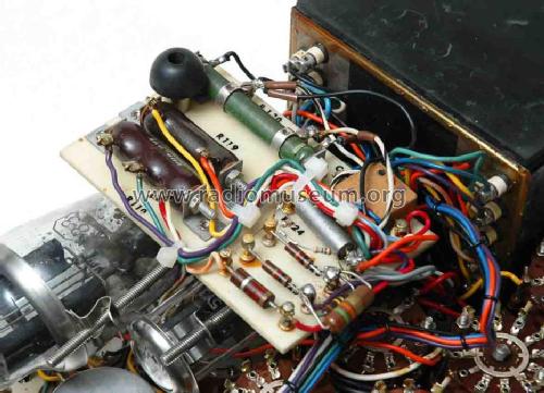
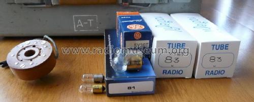
I have a TV7/U,it use a bulb as a fuse.It is important to use the correct type: 81,(6,5V,1,02A;6,6W).
I have found that types 81 & 47 (pilot lamp) bulbs are used in Gottlieb flippers, so it is easy to buy them at sellers of flippers spares parts (in France there is one on Ebay.fr,he sell box of 10 at very reasonnable price)
On the picture,the; yellow bulb is original (GE81),he silver one is a 81 for flipper (exactly similar to original).
I have tested the spares,they runs as originals ones.Using european cars 6V bulbs is also a solution,but they do not complies exactly (6V; 5W ),flippers spares are preferables.
Olivier Palix
Pièces jointes
Olivier Palix, 12.Sep.15
TV-7 military tube testers are appreciated and widely used because of their versatility, ruggedness and simple operation. Unfortunately the meter just gives arbitrary values, from 0 to 120, and data tables indicate the minimum acceptable value for each tube.
But the arbitrary values of the meter can be easily converted to the actual mutual conductance Gm, expressed in micromhos, using the table below.

Intermediate values can be readily calculated by linear interpolation.
The table comes from the TM 11-6625-274-12 manual, covering models TV-7/U, TV-7/AU, TV-7/BU and TV-7/DU. Probably it should also apply to TV-7/CU.
Emilio Ciardiello, 27.Dec.09