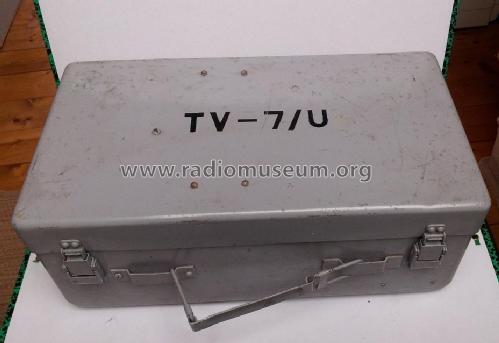
Tube Tester TV-7 U
MILITARY U.S. (different makers for same model)
- País
- Estados Unidos
- Fabricante / Marca
- MILITARY U.S. (different makers for same model)
- Año
- 1953 ?
- Categoría
- Aparato de medida y servicio (Equipo de laboratorio).
- Radiomuseum.org ID
- 68935
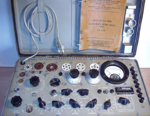
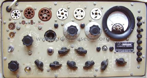
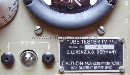
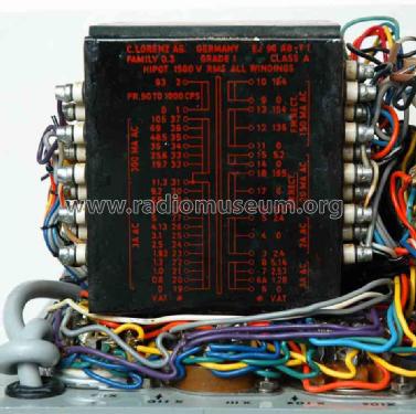
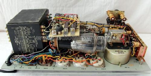
This TV-7/U was build in Germany by Lorenz
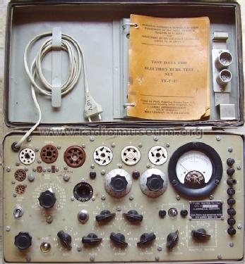
From eBay France N°:331165593414
From eBay France N°:331165593414
From eBay France N°:331165593414
From eBay France N°:331168578026
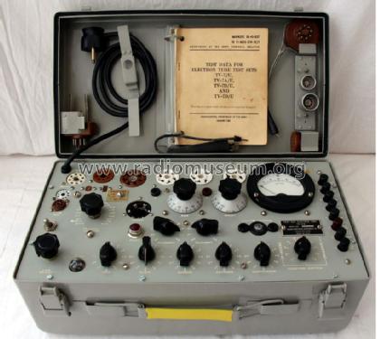
TV7/U état de marche,Armée Française
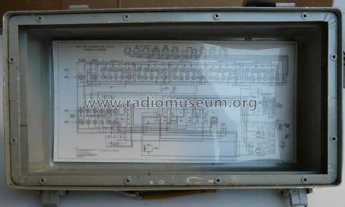
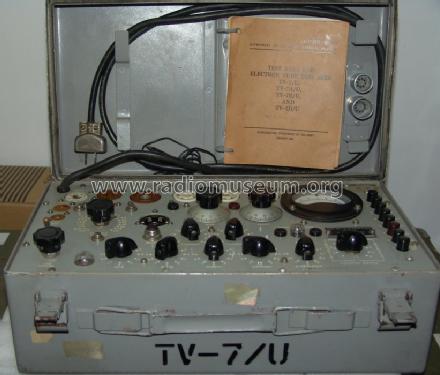
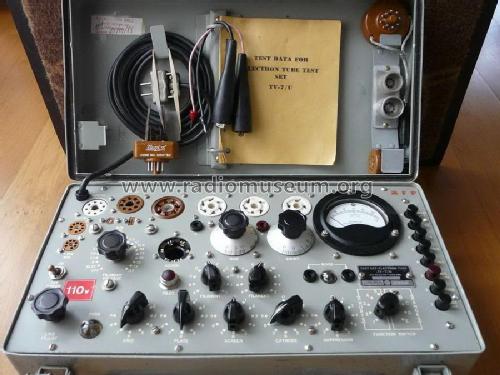
Coffret avec schéma
Haga clic en la miniatura esquemática para solicitarlo como documento gratuito.
- Numero de valvulas
- 2
- Gama de ondas
- - no hay
- Tensión de funcionamiento
- Red: Corriente alterna (CA, Inglés = AC) / 105-125 Volt
- Material
- Metálico
- de Radiomuseum.org
- Modelo: Tube Tester TV-7 U - MILITARY U.S. different makers
- Forma
- Sobremesa de cualquier forma, detalles no conocidos.
- Ancho, altura, profundidad
- 440 x 220 x 155 mm / 17.3 x 8.7 x 6.1 inch
- Anotaciones
-
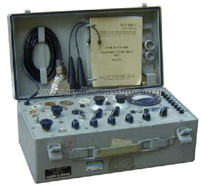
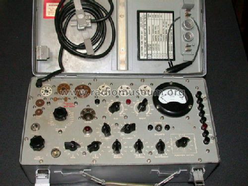
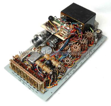
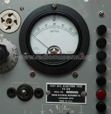
Tube Tester TV-7 /U.
This model /U was built by Supreme.
This model was also produced for NATO by Lorenz, Germany.
- Ext. procedencia de los datos
- Ralf Sürtenich
- Documentación / Esquemas (4)
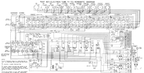
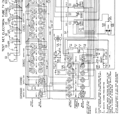
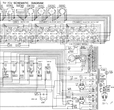
- -- Schematic
- Otros modelos
-
Donde encontrará 394 modelos, 346 con imágenes y 210 con esquemas.
Ir al listado general de MILITARY U.S. (different makers for same model)
Colecciones
El modelo Tube Tester es parte de las colecciones de los siguientes miembros.
Contribuciones en el Foro acerca de este modelo: MILITARY U.S.: Tube Tester TV-7 U
Hilos: 2 | Mensajes: 7
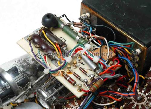
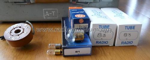
I have a TV7/U,it use a bulb as a fuse.It is important to use the correct type: 81,(6,5V,1,02A;6,6W).
I have found that types 81 & 47 (pilot lamp) bulbs are used in Gottlieb flippers, so it is easy to buy them at sellers of flippers spares parts (in France there is one on Ebay.fr,he sell box of 10 at very reasonnable price)
On the picture,the; yellow bulb is original (GE81),he silver one is a 81 for flipper (exactly similar to original).
I have tested the spares,they runs as originals ones.Using european cars 6V bulbs is also a solution,but they do not complies exactly (6V; 5W ),flippers spares are preferables.
Olivier Palix
Anexos
Olivier Palix, 12.Sep.15
TV-7 military tube testers are appreciated and widely used because of their versatility, ruggedness and simple operation. Unfortunately the meter just gives arbitrary values, from 0 to 120, and data tables indicate the minimum acceptable value for each tube.
But the arbitrary values of the meter can be easily converted to the actual mutual conductance Gm, expressed in micromhos, using the table below.

Intermediate values can be readily calculated by linear interpolation.
The table comes from the TM 11-6625-274-12 manual, covering models TV-7/U, TV-7/AU, TV-7/BU and TV-7/DU. Probably it should also apply to TV-7/CU.
Emilio Ciardiello, 27.Dec.09