- Country
- Netherlands
- Manufacturer / Brand
- Philips; Eindhoven (tubes international!); Miniwatt
- Year
- 1955/1956
- Category
- Broadcast Receiver - or past WW2 Tuner
- Radiomuseum.org ID
- 29950


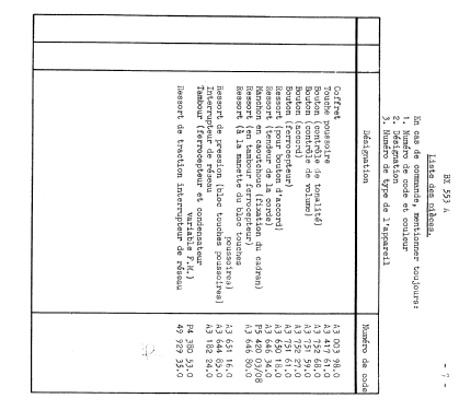

Q: Philips Katalog (NL) 1956

Q: Philips Katalog (NL) 1956


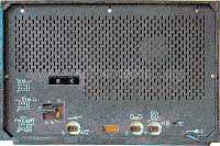

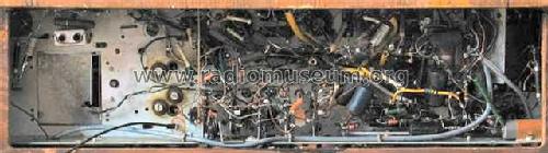
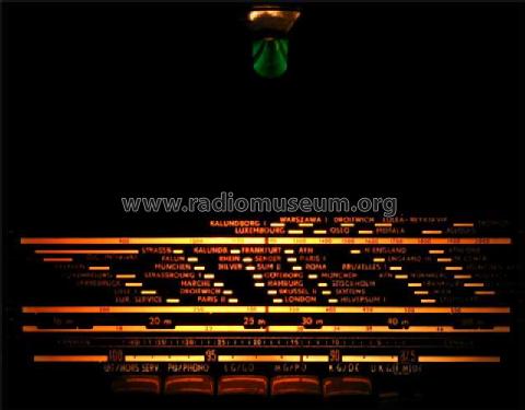

Bild ebay Verkäufer: pittbulltyson

Bild ebay Verkäufer: pittbulltyson
aus ebay, Verkäufer retro0_7

aus ebay, mit Erlaubnis des Verkäufers em85

aus ebay, mit Erlaubnis des Verkäufers em85

aus ebay, mit Erlaubnis des Verkäufers em85


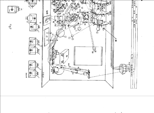
Click on the schematic thumbnail to request the schematic as a free document.
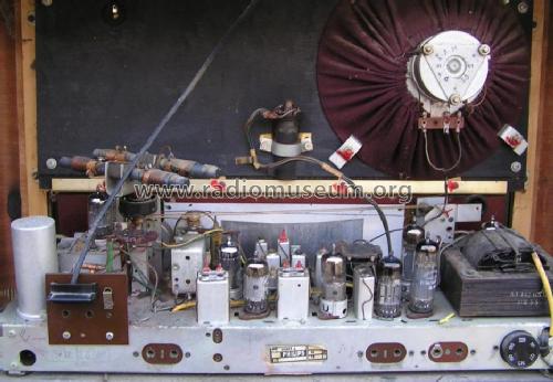
- Number of Tubes
- 9
- Main principle
- Superheterodyne (common); ZF/IF 452/10700 kHz; 2 AF stage(s)
- Tuned circuits
- 6 AM circuit(s) 12 FM circuit(s)
- Wave bands
- Broadcast, Long Wave, Short Wave plus FM or UHF.
- Power type and voltage
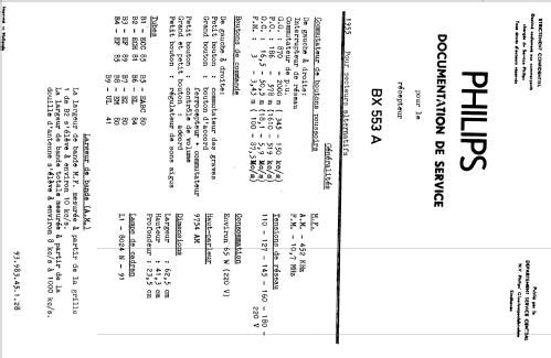
- Alternating Current supply (AC) / 110, 127, 145, 160, 180, 220 Volt
- Loudspeaker
- Permanent Magnet Dynamic (PDyn) Loudspeaker (moving coil) / Ø 19 cm = 7.5 inch
- Material
- Wooden case
- from Radiomuseum.org
- Model: BX553A - Philips; Eindhoven tubes
- Shape
- Tablemodel with Push Buttons.
- Dimensions (WHD)
- 625 x 413 x 235 mm / 24.6 x 16.3 x 9.3 inch
- Notes
-
AM radio with built-in ferroceptor:
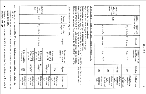
- LW: 150 - 345 kHz.
- BC: 519 - 1610 kHz.
- SW: 5,9 - 18,1 MHz.
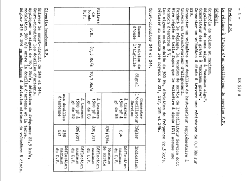
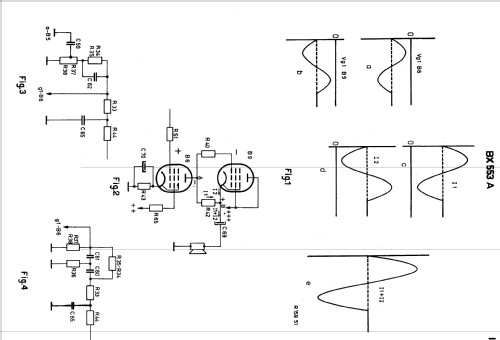
FM radio with dipole antenna input: 87,5 - 100 MHz.Amplifier: SRPP1 type.Loudspeaker: 9754AM (800 Ohm, co-axial).Dial lamp: 8024N (6.3V / 300mA, bajonet).1shunt regulated push-pull amplifier
- Net weight (2.2 lb = 1 kg)
- 12 kg / 26 lb 6.9 oz (26.432 lb)
- Price in first year of sale
- 378.00 Dfl
- Source of data
- Guida Pratica Antique Radio III (2000)
- Literature/Schematics (1)
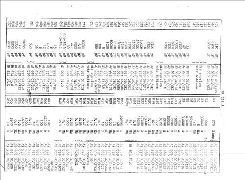
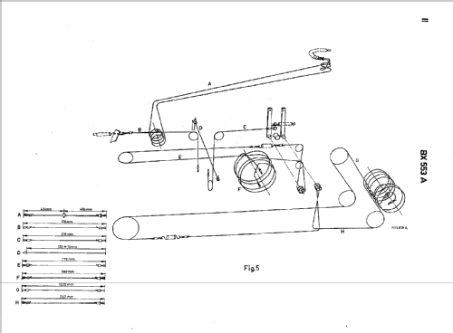
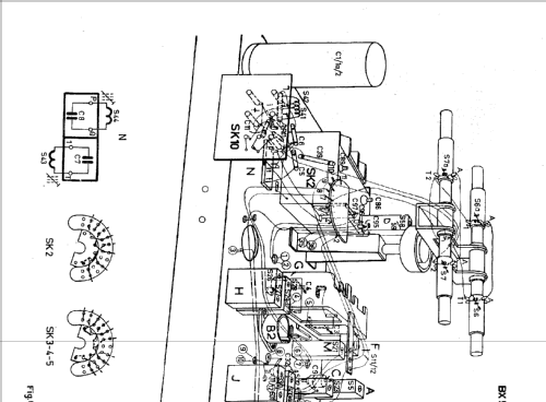
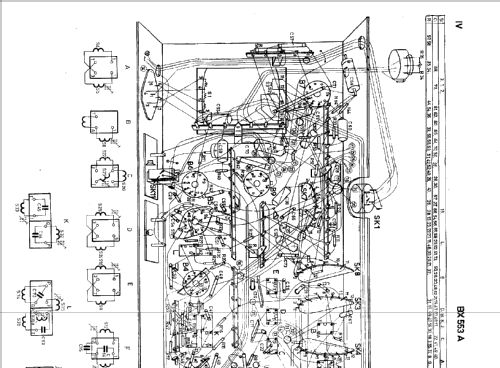
- -- Original-techn. papers.
- Author
- Model page created by Iven Müller. See "Data change" for further contributors.
- Other Models
-
Here you find 5280 models, 4428 with images and 3461 with schematics for wireless sets etc. In French: TSF for Télégraphie sans fil.
All listed radios etc. from Philips; Eindhoven (tubes international!); Miniwatt
Collections
The model is part of the collections of the following members.
Forum contributions about this model: Philips; Eindhoven: BX553A
Threads: 2 | Posts: 16
Gentlemen,
Where may I find an alignment procedure for this radio chassis?
Thanks,
Paul.
Paul E. Pinyot † 2013, 13.Jan.10
Hallo,
ich habe dieses Gerät erworben in einem sehr schönen Zustand. Aber ich verstehe nicht warum hier eine UL41 mit einer EL84 kombiniert wird. Was rechtfertigt den Aufwand einer extra Heizwicklung für die UL41?
Gruß
Franz-Josef
ich habe dieses Gerät erworben in einem sehr schönen Zustand. Aber ich verstehe nicht warum hier eine UL41 mit einer EL84 kombiniert wird. Was rechtfertigt den Aufwand einer extra Heizwicklung für die UL41?
Gruß
Franz-Josef
Franz-Josef Haffner, 04.Jul.05