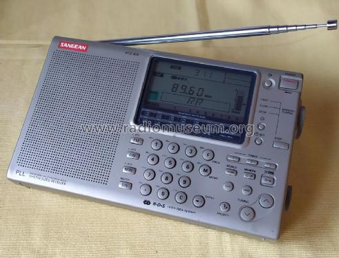
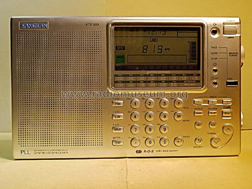
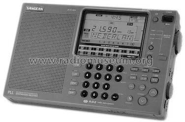
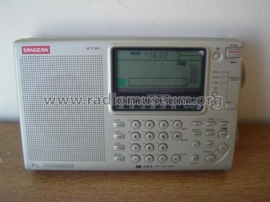
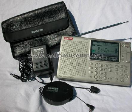
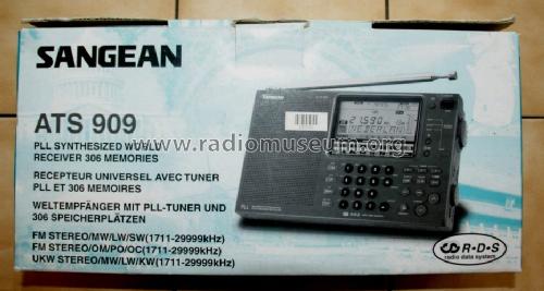
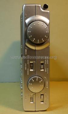
ATS-909
Sangean; Chung Ho City
- Country
- Taiwan (Republic of China)
- Manufacturer / Brand
- Sangean; Chung Ho City
- Year
- 1996
- Category
- Broadcast Receiver - or past WW2 Tuner
- Radiomuseum.org ID
- 78947


Copyright by Rainer Jürgensen


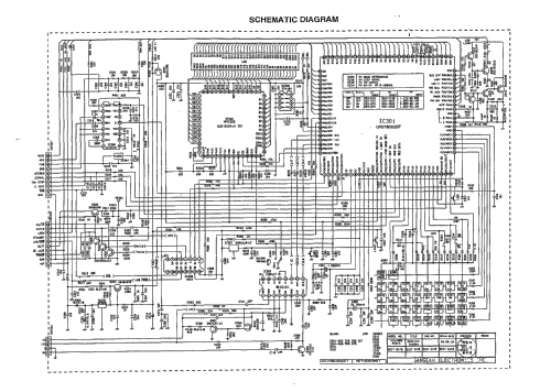
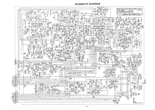
Click on the schematic thumbnail to request the schematic as a free document.
- Number of Transistors
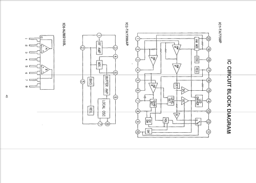
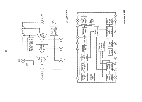
- Semiconductors present.
- Semiconductors
- Main principle
- Superhet, double/triple conversion
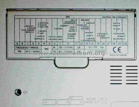
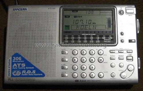
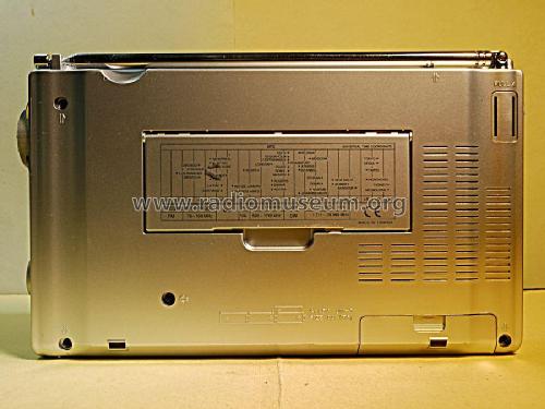
- Wave bands
- Broadcast, Long Wave, more than 2 x SW plus FM or UHF.
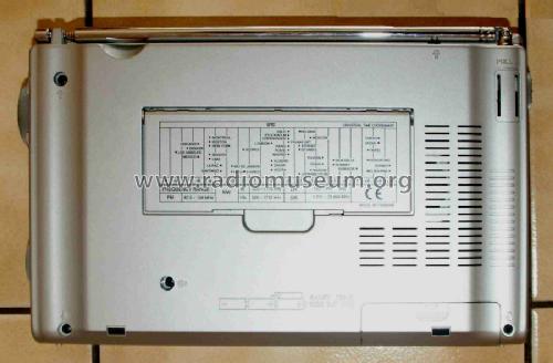
- Power type and voltage
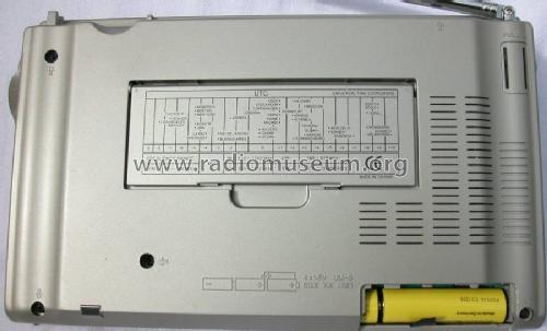
- Batteries / addl. power jack / 4 × 1,5 / 6 Volt
- Loudspeaker
- Permanent Magnet Dynamic (PDyn) Loudspeaker (moving coil) / Ø 7 cm = 2.8 inch
- Power out
- 0.3 W (unknown quality)
- Material
- Plastics (no bakelite or catalin)
- from Radiomuseum.org
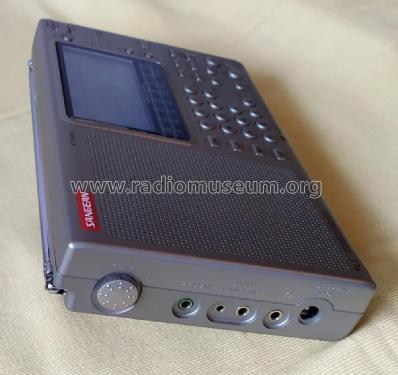
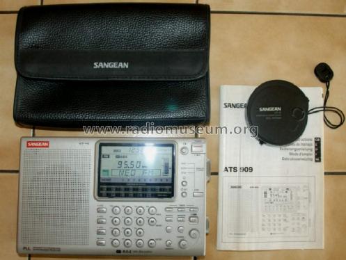
- Model: ATS-909 - Sangean; Chung Ho City
- Shape
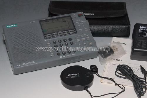
- Portable set > 8 inch (also usable without mains)
- Dimensions (WHD)
- 215 x 133 x 38 mm / 8.5 x 5.2 x 1.5 inch
- Notes
-
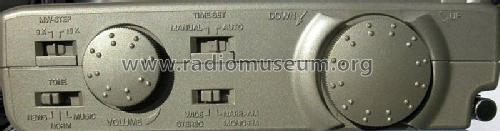
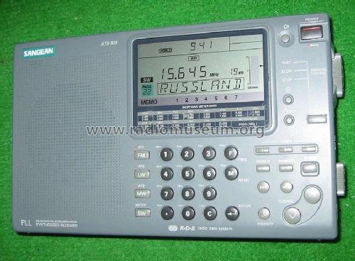
AM coverage 153 - 29999 kHz, AM, SSB (BFO), two IF bandwidths (6.5/4 kHz),
direct frequency keypad entry, 306 partly pre-programmed alphanumeric memories, clock / timer, RDS on FM,
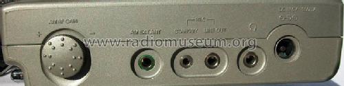
also sold as Siemens RK-777, Radio Shack DX-398. New variant Model ATS-909W appeared later. Ext. Power jack DC 6 V.Siehe auch Lizenz-Nachbau Technisat ATS909.
- Net weight (2.2 lb = 1 kg)
- 0.8 kg / 1 lb 12.2 oz (1.762 lb)
- Price in first year of sale
- 260.00 $
- Author
- Model page created by Martin Bösch. See "Data change" for further contributors.
- Other Models
-
Here you find 77 models, 76 with images and 31 with schematics for wireless sets etc. In French: TSF for Télégraphie sans fil.
All listed radios etc. from Sangean; Chung Ho City
Collections
The model is part of the collections of the following members.
Forum contributions about this model: Sangean; Chung Ho: ATS-909
Threads: 4 | Posts: 7
I got this nice radio in good working order.
Current consumption looks normal to me. 60uA when turned off, 65mA on FM and 68mA on SW at minimum volume, and around 100mA at nearly maximum volume.
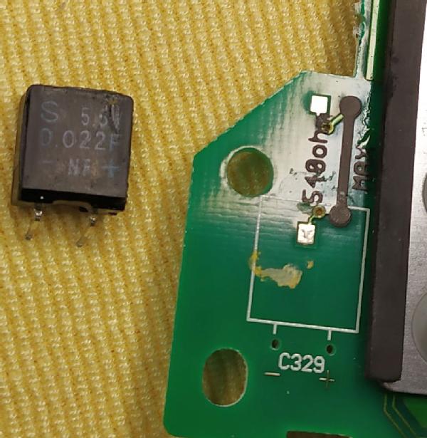
However, I realized that it is not able to retain the memory presets nor the clock time as soon as the four dry batteries are removed.
This issue seems to be caused by a common fault of the super capacitors of certain types and age. This one looks kind of dated in terms of packaging when compared to the disc types manufactured these days.
My radio have date code of 2003, so this 5.5V 0.022F supercap encapsulated in a plastic square box have now about 20 years since it was produced.
To my capacitor tester, it looks like a open circuit with just parasitic capacitance of few nanofarads. Resistance reading is around 15 MOhm. Trying to charge it with 3V and then reading with a 10MOhm multimeter shows just residual storage volage at around 0.1V. So it lookd dead.
Time to search for a new, encapsulated like the original, supercap, maybe someone still have these as new old stock items.


Jose Mesquita, 08.Sep.22
It seems that this radio had a fairly long production life, starting in 1996 and went at least to 2007 according to the pictures/videos found publicly showing PCB's date codes. As the 909X replacement model was released in 2011, we may infere that the 909 probably was available until this later date.
The only service manual available is dated from 1997, so it lists the original part numbers and original design. It would make sense that later chassis revisions were released along all these production years, but I could not find clear evidence of what has been changed.
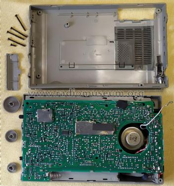
PCB assembly releases
(Information based on the service manual and on pictures/videos found publicly)
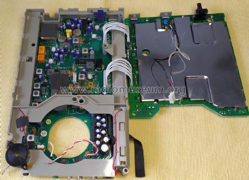
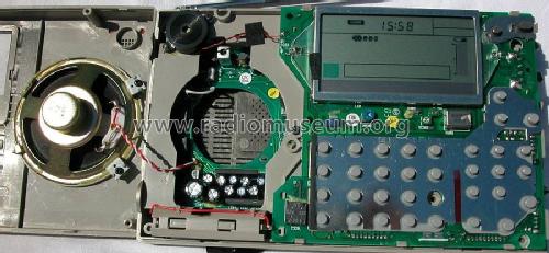
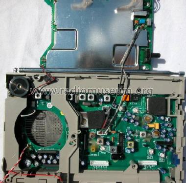
- Receiver PCB assembly identified as "PCB A ATS-909" in the service manual
- P/N 1611600 label on the PCB, date code of 9852 (1998 week 52)
- P/N 1611601 label on the PCB, date code of 0323 (2003 week 03) -> my unit
- MCU/DISPLAY/KB assembly identified as "PCB C ATS-909" in the service manual
- P/N 1611150 label on the PCB, date codes 9808 (1998 week 08), 0315 (2003 week 15), 0706 (2007 week 06)
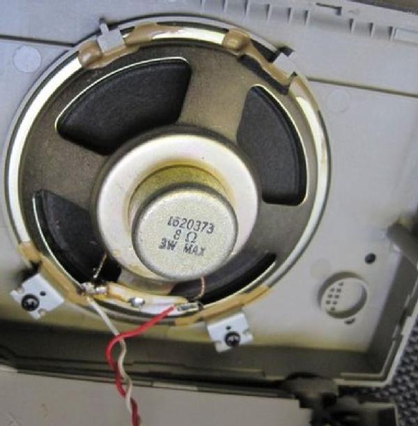
Loudspeaker releases
Concerning the loudspeaker component, several part numbers were released.
It seems that the initial production used a large but not shielded magnet, taking almost all the 49mm hole in the "PCB A" receiver assembly.
Later on, Sangean switched to shielded loudspeakers, despite using much smaller magnets. This move makes sense to me, as there are sensitive RF coils, some without shielding (at least on later chassis revisions), around the magnet.
Later vaersions kept using shielded magnets, but with larger sizes.
Independently on the speaker variants, the common allowed loudspeaker characteristics would be:
- Electrical: 8 Ohm, 3 Watt maximum, shielded magnet
- Physical: 77 mm diameter x 30 mm maximum height, 44.5mm magnet maximum diameter
The following lists my findings based on my own radio unit and on the publicly available documents, pictures/videos.
- From 1997 Service Manual:
- P/N 1620370/1 "SP 3" 8 OHM 3W 77x29.1mm"
- Found information:
- Seen on speaker label: "1620370 8OHM 3W (MAX)"
- Large, not shielded, ferrite magnet, around 44.5mm diameter
- Video clip. MCU PCB seems to have a 1996 date code (9643?).


- P/N 1620373 "8OHM 3W MAX" as seen on speaker label
- Small shielded magnet around 20mm diam
- Seen after 1998 and at lest up to 2003 radios
- Used as well on my gold cabinet/red logo revision with 2003 PCB date codes.


- P/N 1620880 "8OHM 3WMAX 18F3" as seen on speaker label
- Large shielded magnet around 35mm diameter
- Unable to find pictures of PCB using this P/N to be able to set a date, despite the code 18F3 could be a date but it does not make sense to me, as the year should be around early to mid 2000 (see next P/N below)

- P/N 1620880-A "8OHM 3W MAX 06J2" (or "06G2") as seen on speaker label
- Large shielded magnet around 35mm
- Seen on 2006 and 2007 radios


- P/N 1620881 "8OHM 3W 2005 02" as seen on speaker label
- Large shielded magnet around 35mm
- Seen on silver cabinet radios, probably from 2005 as seen on the speaker date code

- P/N 1620883-A "8OHM 3W MAX 10E2" as seen on speaker label
- Large shielded magnet around 42mm
- Seen on Silver cabinet radio
- Unable to find pictures of PCB using this P/N to be able to set a date. However, the speaker had what I believe can be a date code "10E2" but these codes seems obscure to me, could it beyear 2010?

Jose Mesquita, 05.Sep.22
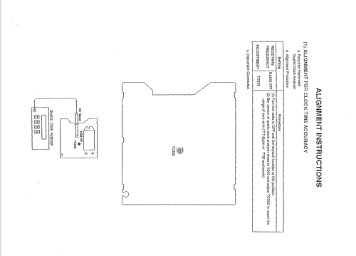
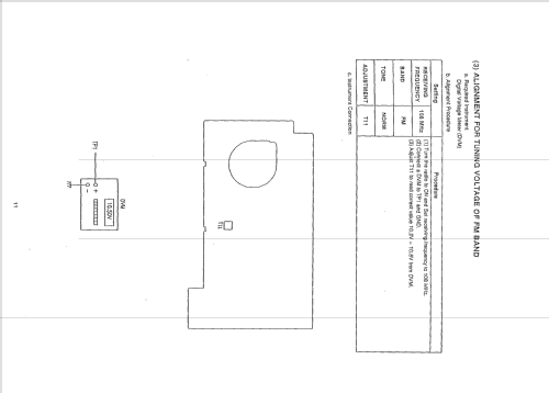
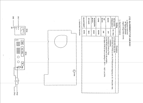
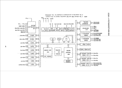
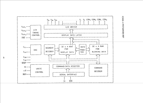
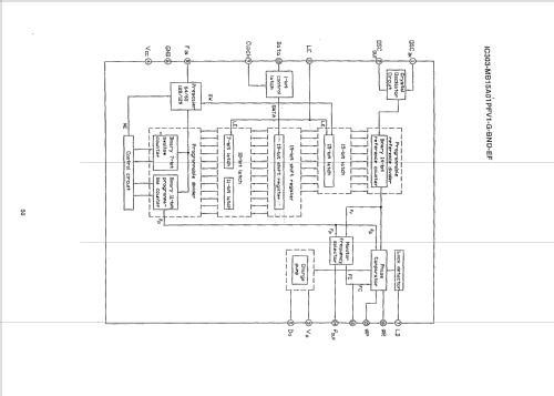
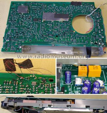
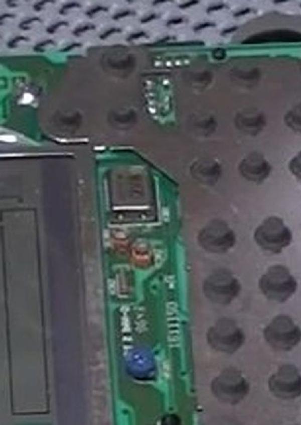
According to the service manual, six signal diodes (like 1N4148) are used to set up the RF Bands coverage at the production stage, depending on the target market.
These diodes are soldered at the MCU Control PCB assembly.
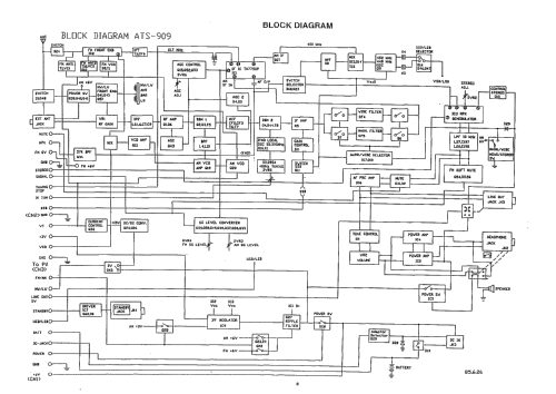
This ATS-909 chassis used on several other brands was very popular among the aficionados and modders around the globe. Among the modifications are the RF band coverage, but other more invasive procedures change the AGC circuit response, the Muting disabled, and sensibility improvement on telescopic antenna (an identified issue with impedance mismatch between the high value of the telescopic antenna and the low value of the two RF Front-End FET's common gate design).
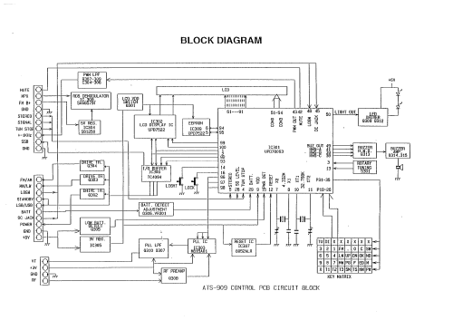
Partial MCU Control schematics:

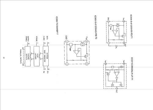
Partial MCU Control PCB layout:
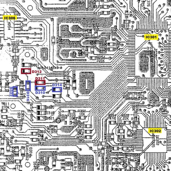
Partial MCU Control PCB picture:

Note: As far as I know, on a common to find radio version marketed in USA and large part of European countries, none of the above six diodes are installed from factory. As such, it would cover FM from 87.5 to 108 MHz with 100 kHz channel steps, LW from 153 to 519 kHz, MW from 520 to 1710 kHz, and SW from 1711 to 29999 kHz.
Jose Mesquita, 24.Aug.22
Das 'W' in der Bezeichnung steht für 'WIDE frequency range' von 76 - 108 MHz.
Franz Harder, 25.Apr.05