A simple charger for Ni-MH battery packs
A simple charger for Ni-MH battery packs

Dear readers,
recently Joe Sousa presented an impressive overview of battery packs he had assembled using off-the-shelf Ni-MH cells; see www.radiomuseum.org/forum/nimh_battery_packs_for_high_voltabe.html. I decided to follow this way to operate some battery radios I own, but soon I faced the problem of the charger: I found many and many low voltage chargers, but nothing working over 12V. For this reason, first I had to build a battery charger for high-voltage packs. No relevance the charge algorithm, cells must be series connected when charged: in this way, the current flowing in all the cells can be safely controlled. I decided for an overnight charge at C/10 current, because fast charging techniques ask for temperature sensors inside the battery pack. To prevent overcharge, when the battery was not fully discharged or when it is left under charge, I added a voltage topping circuit. 1.41V per cell can be a good approximation for the end of charge limit in home use, around 20 degrees C.
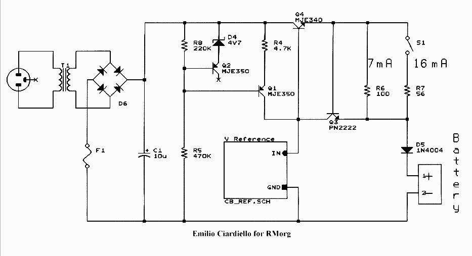
Here is the diagram of a charger capable of charging batteries of the above voltages with 70 or 160mA/h capacity. The circuit is quite simple and flexible and can be readily adapted to any number of series cells and to any cell capacity.
forumdata/users/6435/file/Battrt_chg/diagram.png
forumdata/users/6435/file/Battrt_chg/reference.png
Two different voltage reference circuits are given, one for single voltage output and the second for multiple voltages. Low temperature coefficient zener diodes should be used, series connected for the wanted voltage; a variable cermet trimmer is added for each range, to have the fine voltage adjustment. Here the values of D1 through D3 and R1 through R3 for the different voltages:
Single voltage reference
Voltage D1 R1
22.5V 4 x 6.2V or 3 x 6.8V 10K, cermet multiturn
45V 8 x 6.2V or 7 x 6.8V 10K, cermet multiturn
67.5V 12 x 6.2V or 11 x 6.8V 10K, cermet multiturn
90V 16 x 6.2V or 15 x 6.8V 10K, cermet multiturn
Multiple voltage reference: 45, 67.5 and 90V
Range Zener diodes Resistive trimmers, cermet
45V D3 = 8 zener diodes 6.2V or 7 x 6.8V R3 = 10K
67.5V D2 = 4 zener diodes 6.2V or 4 x 6.8V R2 = 10K
90V D1 = 4 zener diodes 6.2V or 3 x 6.8V R1 = 10K
Of course, more voltages can be added if required. A transformer with a 110V secondary, followed by a bridge rectifier is used. Lower voltage secondary winding, such as 24V, followed by a voltage doubler or tripler, can be used if just lower voltage packs are to be handled. Q1 works as current generator to drive the reference circuit with 1mA constant current. Transistor could be any high-voltage PNP, with Vceo higher than 150V: also TO92 types, as BF423, BF493, or equivalent, can be used. Q2 could be the same type for better Vbe matching, but a 1N4148 does the same job. R4 must be a metal film stable resistor.
MJE340 or any equivalent, TO126 or TO220, high-voltage medium power NPN can be used for Q4, the series pass regulator. A suitable heatsink is required and Q4 must be electrically insulated, since its collector is at about +150V. Q3, the current limiter, is a general purpose NPN, PN2222 or any other equivalent. Switch S1 is left open for 70mA/h cells, or 7mA current limit; when closed, the current limit is raised to about 16mA, for charging 160mA/h batteries.
The charge current limit can be checked with a DC milliammeter between the two out leads, about 7ma for 70mA/h cells or about 16mA for 160mA/h batteries. The voltage reference trimmers can be adjusted reading the open circuit voltage on the battery out leads for the charge voltage value corresponding to the selected range.
Nominal voltage of the battery pack Series cells qty. Charge voltage at 20 deg.C
22.5V 18 25.4 V
45 V 36 50.8 V
67.5 V 54 76.1 V
90 V 72 101.6 V
I also ran a simulation of the single voltage circuit. Here are the diagram, the .cir file, the out plot and a picture of the very early breadboard.
forumdata/users/6435/file/Battrt_chg/Simul.jpg

Regards, Emilio
To thank the Author because you find the post helpful or well done.
Current vs Voltage charging

Emilio,
Thank you very much for extending the topic of NiMH chargers to high voltage. This will be very useful for packs that are permanently configured in series for high voltage. I have some of these, myself.
Current charging and voltage charging are different methods with different goals in mind.
The current charging method is the fastest method, but the final voltage must be monitored. This tends to cause the highest wear on the batteries if high charging currents are used, and also has a higher potential for overcharging. But this is not the case presented here by Emilio.
The case presented here is for limited low current at the recommended manufacturer rate of C/10h, where C is the battery capacity in mAxh and 10h is 10 hours. The charge efficiency is less than 100%, so the total charge time will be more than 10h.
Emilio's current limited method of charging is much faster than the voltage limited method I proposed, even when the conservative current limit of C/10h. The 1.41V per cell voltage limit also ensures that the batteries will not be damaged with overcharging, and helps equalize the pack voltage.
The voltage method of charging is inherently exponential in current, so it may take several times longer for a full charge.
One significant advantage of parallel voltage charging is that it can be done indefinately with 1.4V, because the current settles under the trickle current charge level, and the pack charge among the various cells remains as well matched as it can be.
Matched battery voltage provides a better measure of charge match than a match in charging current. This is especially true as the pack ages and the capacity on some cells starts to drop. Ageing packs also benefit from storage in shunt configuration, so that the weakest cell remains charged by the stronger cells.
Regards,
-Joe
To thank the Author because you find the post helpful or well done.
Design compromise
Dear Joe,
many thanks for your comments. The circuit I proposed however controls both voltage and current. When the charge starts, current is limited to the safe value of C/10 which anyway avoids dangerous overheating. When the charge is more or less complete, the battery voltage approaches the output voltage of the charger and the current drops near to zero (trickle charge). In the parallel charge, at the start, the current in each cell is not limited at all. In normal circumstances, the voltage increases rapidly and the current decreases as the cell’s voltage approaches the value of the charger out. In some circumstances, as in the case of faulty cells, the charge current can well exceed the manufacturer’s maximum value, with the risk of explosion.
I do not see substantially different behavior between parallel or series charging when trying to charge weak elements. In this case, the voltage may reach the equilibrium but the charge capacity is negligible and the voltage drops again quickly when any load is connected to the battery.
The proposed circuit differs from a fixed voltage supply, the one anyway needed for parallel charging, just for the addition of two inexpensive components to limit the current, Q3 and R6.
The true limit of this circuit is in the variation of the battery voltage with temperature. The circuit works fine at more or less 20 degrees C, but the battery may result overcharged or undercharged if the temperature rises to 40 degrees C or drops under 10 degrees C. I left this problem open, since this charger should be used at home, where extreme temperatures should not be encountered. The operating temperature range could be expanded if needed, adding some temperature compensation on the voltage reference. In the given circuit, the temperature behavior can be easily controlled, just compensating the current generator, which drives the voltage reference.
Other charge techniques are just theoretical or hardly applicable in the case of high-voltage packs. The time limited charge, 12 hours at I=C/10, just works safely when the battery is fully discharged, otherwise severe overcharges may result. I remember some stupid battery charges for mobile phones, where a discharge cycle was run before the charge started: the result was that often the user picked up his mobile from the charger when the discharge cycle was ended, with the battery fully discharged.
One fast charging technique is based upon the effects of gas generation at the end of the charge. The resulting voltage rise can be monitored with a simple -dV/dt detecting circuit, as in the figure below. When the voltage ceases to increase or starts to decrease, the charge is ended.

Unfortunately the voltage variation was well pronounced in the old Ni-Cd batteries, where gas gave also the so called ‘memory effect’, but it is much less evident in the Ni-MH cells. Actually manufacturers ask for a combined temperature rise monitoring, a dT/dt sense circuit in addition to the –dV/dt, when using high charging current. And they also suggest to use the highest possible charge current, to have a more pronounced temperature increase, otherwise masked by room temperature fluctuations. Now, a temperature sensor can easily be placed inside a two or three cell battery. The questions are where to place a sensor in a 72 cells battery pack to rapidly detect a sudden temperature increase, or how many sensors are required to control the temperature of a significative number of cells.
The proposed circuit can then be considered a simple, yet acceptable compromise to the problem of charging high voltage battery packs.
Regards, Emilio
To thank the Author because you find the post helpful or well done.
A good range of design choices.
Dear Emilio,
Thank you ver much for broadening the NiMH topic. You added good new material. This can only give potential users more choices.
I considered the issue of high currents when batteries are suddenly connected in parallel. It is not much of an issue with the small batteries I have been using with capacities under 150mAH. When shorted together, or when the 1.4V is applied to a discharged pack, the high current spike is less than 0,5A, if for no other reason because of the wiring. It only lasts a few seconds, and I include crude current limiting in the form of light bulbs, resistors, or even the current limit of the regulators to keep heat under control.
Nearly all my home lab designs are driven by what I have in the lab. This is part of the fun for me. You probably do the same.
If I were dealing with NiMH batteries with more than 1AH capacity, I would pay much closer attention to maximum currents. Batteries at, or above, this capacity can easily melt wires and start a fire. I just remembered that I have a high capacity pack pack in my home lab for general use and I included a circuit breaker. The larger packs for filaments should always be fused, and it is a good idea to add fuses to the HV packs too.
Another problem with shunt charging 9V format batteries is the risk of momentarily reverse connecting a cell to a shunt pack that already has several cells. This should only cause a warning spark, which will be quite startling. This not an issue for the hard-wired shunt-parallel packs in a card edge socket, or for packs with hard wired ganged switches, as I showed in the original post.
One characteristic of most NiMH batteries is that they can supply very high currents, or accept very high currents for short periods, as long as they are not over-charged.
The initial discharge cycle was used sometimes for NiCd (Nickel-Cadmium) because this chemistry had a tendency to not charge fully, unless it had been completely discharged. This is the complete opposite problem for Lithium Ion batteries, that can be damaged with a full discharge. Lithium batteries also decay from always being at full charge. This is the case for laptops that are plugged in most of the time.
NiMH cells don't suffer from either problem, but, of these three technologies, NiMH batteries are the most difficult to charge quickly, because the voltage rise is a very weak voltage rise over time that is hard to detect. Hard for analog or digital circuits to remember a few mV over many minutes.
I have at least one commercial NiMH pack that uses the temperature sensing method. This raised temperature always makes me wonder how much battery life is being sacrificed. Most chemical processes of decay tend to double every 10oC. The temperature rise is usually under 20oC, and it does not happen for very long. It just bugs me a bit.
Along the lines of reducing battery life, I wonder how much is lost in the voltage rise method that allows for some gas generation. Probabably not a significant loss in battery life. It just bugs me too.
Regards,
-Joe
To thank the Author because you find the post helpful or well done.
Design approach
Dear Joe,
as usual, you gave a broad and detailed overview of the matter. No doubt that, in normal condition, the peak current at the start is of short duration. Within few minutes, the voltage of the cell under charge considerably approaches its final value and the charge current decreases in accordance with Ohm’s law.
Nevertheless, I use to consider possible fault conditions, including shorts and/or parametric deviations. When a battery pack contains some 72 cells, you can easily have defective elements through its life. It is true, it is just philosophy, but in the years I have seen how many irreparable damages can be made to complex and expensive equipment by the explosion of a small lithium backup battery; or even by the acid leaking through a defective sealing gasket. Small batteries can just deliver small heath, but also their heath dissipation is very poor. If anything can go wrong, it will…
For this reasons, I use to refer to the manufacturer’s recommendations and stay well within the specified limits for that family of components, no exception. This guideline should be particularly true for unbranded components, as many Chinese batteries are. For most of them you cannot find a data sheet: how can you rely upon a repetitive value of current, self-limited to, say, 0.5A for each of them? In designing the above circuit I referred to the application notes of the few Japanese manufacturers still present on the web in this segment, Sanyo and Panasonic. Of course, their application notes refer to high-quality batteries for specific uses, since probably they are no longer directly involved in manufacturing button cells. So, when dealing with unbranded batteries, I try to be still more conservative on the limits given in the documentation of serious manufacturers.
I fully agree with your perplexity on the temperature sensing charge termination. With Ni-Cd cells, the temperature sensor was used as safety device, the charge being monitored by a –dV/dt circuit. But now the charge is just controlled by monitoring the battery overheating and I do not know what happens inside the cells before heath reaches the sensor. It is one of the reasons why I opted for a C/10 charge technique. The other reason is that anyone who wants to revive an old battery radio cannot be so in hurry to need charging the batteries in few minutes.
For my own temporary use, I could do the job with a diode and a resistor. But I had decided to build a general purpose charger for some battery packs I am going to assemble. After that, I decided to share its diagram with other people, which could have similar needs. Therefore I had to give a reliable circuit, operating with several types of batteries and easily replicated and operated. The safety of operation, even when left unattended, was therefore of the utmost importance upon the life of the battery itself. I am also considering the addition of a zener diode or of a crowbar SCR in parallel to the battery, to protect the same in the case of a collector to emitter short in the series pass transistor Q4.
I would appreciate any further advice.
Regards, Emilio
To thank the Author because you find the post helpful or well done.