Background hum with electrodynamic loudspeakers
Background hum with electrodynamic loudspeakers

The presence of unpleasant levels of background hum is a non invited visitor that sometimes plagues restoring projects. Hum can be caused by several reasons; this note has been spurred by a practical case concerning the restoration of a Siemens 37WLK where the phenomenon was particularly evident but the considerations that follow can be applied to all receivers endowed with electrodynamic loudspeakers. The field coil of these speakers, quite common in the 30s, has been almost invariably used as filter choke for the power supply; the partial diagram of the SH 37WLK (courtesy of Dietmar Rudolph) reported below (all non essential elements have been removed) is a typical example.

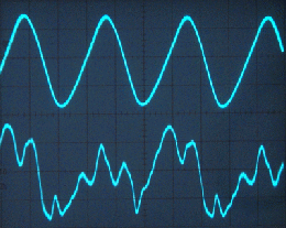
It can be observed that the input and output capacitors of the filter (C1 and C2) have a modest value (4 uF); this is due to the fact that these capacitors are not of the electrolytic type but high-quality bulky paper capacitors. As a consequence, the ripple on C1 (point A) is quite high while the ripple on C2 (point B), because of the high value of the field coil inductance, is modest and completely compatible with a humless operation of the receiver. This design, however, leads to a substantial amount of ripple current in the field coil and, consequently, to a modulation of the magnetic field in the air gap where the voice coil is inserted. The (modest) ripple on the plate of the final tube (RENS 1374D) determines a modest hum voltage on the primary and secondary windings of the output transformer and, consequently an associated hum current in the voice coil. The force acting on the voice coil in a generic instant of time is proportional to this current and to the intensity of the magnetic field at the air gap which, in turn, is proportional to the current flowing in the field coil. The force acting on the loudspeaker cone is thus proportional to the product of the hum current and of the ripple-modulated current across the field coil. These currents have the same period and the acoustic pressure generated by their presence depends not only on their intensity but also on their phase relation; by inverting the connection of the field coil or that of the primary winding of the output transformer we can introduce a phase shift of 180 degrees and, in general, the two possible connections will correspond to different levels of background hum. On the same set, however, and with the same connection of the primary winding of the output transformer, the field coil connection associated with the lower hum level will always be the same. The picture below shows the modulation of the magnetic field at the air gap (upper trace) measured through the voltage induced in the disconnected voice coil and the hum voltage at the secondary winding of the output transformer (voice coil disconnected) in a restored SH 37WLK.
In the SH 37WLK the hum can find several paths (the metal shield under the chassis, for instance, is absolutely necessary) but no hum had been observed during the restore procedure, it appeared only after inserting the chassis in its cabinet. The only variation that had been performed in this phase concerned the final wiring of the field coil and, after its inversion, the background hum returned to an almost inaudible level. The substantial amount of the perceived variation has induced to perform a measure of the associated variation of acoustic pressure; the obtained value has been -8.2 dB. A comparable effect could be obtained, in a less elegant way and by introducing an additional component, by increasing the value of C1 from 4uF to 33uF in order to substantially reduce the ripple current across the field coil.
Despite the relevance of the consequences of the inversion of the field coil connections (or, equivalently, of the primary winding of the output transformer), no indication is usually given on the electrical diagrams of the receivers endowed with electrodynamic loudspeakers; this practice, however, belongs to the list of “tricks” suggested to get rid of hum. The loudspeaker designed by Telefunken and mounted on the SH 37WLK (see next picture) has, in fact, different terminal connectors on its field coil that denote where they should have been connected; one of the terminals is designed for the connection to a single wire (point A on the diagram, single wire from the chassis) while the other is designed for the connection to a pair of wires (output transformer, mounted on the loudspeaker frame, and point B on the diagram, single wire from the chassis).

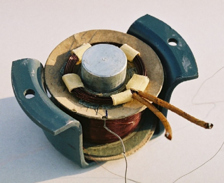
It is possible to find on the SH 37WLK also a completely different loudspeaker, designed by Siemens, that does not exhibit any difference between the voice coil connections as shown in the following picture.

To thank the Author because you find the post helpful or well done.
Input capacitor value

Dear Roberto,
I guess that your thread is someway related to the specific Siemens SH 37WLK model, even if some tips can be applied to other radio sets.
Greatest care to prevent wire inversions should always be used when connecting voice and field coils of electrodynamic speakers. Hum was carefully controlled by design in old radios. In some cases an additional winding on the field coil was connected in series to the voice coil winding, to intentionally add a 180 degrees out of phase ripple to the useful audio signal and cancel the hum coming from the ripple in the field coil itself. Not clear if the input capacitor was actually increased to 33 uF in this set.
Unless specific current limiting circuits or devices were used, any excessive increase in the value of the input capacitor should be avoided or carefully evaluated. For high capacitance values, the ripple reduction always leads to a reduction of the conduction angle and consequently to very high peak currents.
In many old radio sets, filter capacitors of quite low value were just used to limit the peak plate current of rectifier tubes to safe values, as specified by tube manufacturers. Typical values given for capacitor-input filters were in the order of 4 microfarad and current limiting devices, as series inductors, were recommended for values above some 10 uF. I do not have data of the rectifier used in your radio set, the RGN1064, but a 4 uF capacitor is given in its application circuit.
Now the replacement of an original 4 uF capacitor with a 33 uF one, to reduce the hum deriving from a cable reversal, might even work fine in this radio, but could damage an already fatigued old rectifier in other sets.
Regards, Emilio
To thank the Author because you find the post helpful or well done.
Hum and filter capacitors
Dear Emilio,
I agree completely with your considerations and particularly with the negative effects of arbitrary increases in the value of the input capacitor in the filter.
In fact, I have indicate the value of 33 uF as an example of the wrong way of treating the problem; this would have been a brute-force approach that would have remarkably increased, without necessitty, the stress on the precious mesh RGN1064 mounted on my SH 37WLK (by the way, the maximum suggested value for the input capacitor for this tube is 60 uF). The test with the 33 uF capacitor has been performed only to countercheck the other measures. My approach in restoring old sets is to avoid with care any modification in the original values of the components in order to respect the integrity of the receivers and also as a form of respect for their designers.
Sometimes I have encountered variations (in particular, larger values of decoupling capacitors) that had been clearly performed at production time, perhaps to use stocks of available components; in these cases I have prefered to avoid changes leaving in place (if efficient) the components with modified values.
Best regards, Roberto
To thank the Author because you find the post helpful or well done.
Thanks for clarification
Dear Roberto,
many thanks for your clarification.
Today it can be quite hard to find low value filter capacitors and often they are hastily replaced with electrolithyc types of higher capacitance. Of course high value capacitors can be used at the filter input. Depending upon the source impedance, the filter input capacitance and the specific rectifier tube, in most cases a current limiting device, even a simple resistor, could be needed to keep the peak current below the value specified for the rectifier. For this reason, should a similar solution be proposed, it must be someway tied on a case by case basis to a given set.
Best regards, Emilio
To thank the Author because you find the post helpful or well done.
Capacitors
An interesting article.
Off topic, but the low value HT capacitors are available as non-Electrolytic foil type. PCB versions of 1uF 400V can be paralleled and also "motor run" capacitors from 1uF to 16uF are available to run 3 phase motor off a single phase supply. A 300V AC rated non-polarised capacitor may be fine to over 420V Peak and a 250V part to 350V peak DC. Consult data sheets.
To thank the Author because you find the post helpful or well done.
Getting proper capacitor values
Hi Michael,
I appreciate your suggestion of using parallel connections of non polarized capacitors and/or capacitors originally designed for heavy AC applications to substitute electrolytic ones in the power supply. From a technical point of view this solution is, in my opinion, very sound and I have relied on it several times in order to maintain the original values, for the reasons clearly described by Emilio Ciardiello. Of course if the purpose is not just repairing but restoring a radio set in a philological way, the possibility of applying this procedure is conditioned by the shape and volume of the capacitors to be substituted. The ideal case concerns capacitors originally contained in metal cases as happens for the SH 37WLK where the 4 uF filter capacitors are contained in the large metal box on the left of the picture.

In fact these capacitors, despite the symbols used in most electrical diagrams, were not electrolytic but of the impregnated paper type so that I would suggest a careful test before deciding for their substitution.
To thank the Author because you find the post helpful or well done.
Ripple polarity
Thanks for reminding us that field/voice coil polarity may reduce hum.
Before the mid 1930s, when electrolytics came into wide use, large filter caps were VERY expensive.
Even then, the first US electros were 4uFd (hence the 4-8-16-32 series of values found in 1940s equipment).
A single-stage filter needs to be 20uFd-60uFd with pentode (more for triode).
But large magnets for speakers were also expensive. Iron and copper field coils were cheaper and also suggested a C-LR-C filter. Ripple reduction is very much improved, allowing smaller capacitors.
As Roberto points out, there is moderate ripple in the field coil and residual ripple at the final amplifier. A correct choice of polarity offers some cancellation of ripple in the sound. If the capacitors absorb "too much" ripple the cancellation is very small, and output ripple rises. This can be "fixed" by making the capacitors 10X to 100X larger, which is inelegant, expensive (except caps today are very cheap), not authentic, and (somewhat) increases rectifier stress.
> no indication is usually given on the electrical diagrams of the receivers endowed with electrodynamic loudspeakers
In some constructions the output transformer and speaker were sold as a unit. The rectifier, B+, and plate polarity, and the field and voice coil polarity, were set by the loudspeaker maker or radio builder. Since builders and repairers did not have to worry about it, the polarities might not be on the repair manual.
Today we may be doing more extensive repairs than simple speaker-unit replacement. Also I think most good repair men "knew" that some hum problems after speaker work suggested lead-swap... such "common knowledge" tricks have been forgotten.
> the hum voltage at the secondary winding of the output transformer (voice coil disconnected)
With pentodes, hum is reduced by loading. The plate B+ ripple is divided between winding and plate resistance. Pentode's Rp is much higher than its best-power load. Most of the ripple is dropped across the tube, not much (~~10%) across the winding. (This was a great benefit over triodes, which typically drop 60% of B+ ripple across the load.) When tested un-loaded, the ripple is split between Rp and the unloaded "load". Ideally the unloaded winding is infinite impedance. In real cases there is uncertain core loss and significant but insufficient inductance. (The inductance is perhaps why your lower trace shows more harmonics than fundamental; a typical radio did not load well below 150Hz.)
To thank the Author because you find the post helpful or well done.
Hum cancellation still used in 1960's

Thank you Roberto for the warning on field coil and transformer polarities. I had not considered this, but it makes perfect sense.
Paul's mention of the advantage of of high pentode plate impedance reminded me that even after Electrolytics were comparatively cheap in the 1960's, hum cancellation of the residual hum that is not rejected by the high plate impedance, was done with a special tap in the primary of the transformer that made the hum rejection of a single ended pentode plate about the same as as the rejection of a push-pull pentode stage.
Pentode and Triode push-pull amplifiers reject plate hum due to the symmetry of the matched plate drives and the common mode rejection of the transformer primary. The power supply hum that is present at the primary center tap is a common mode signal to the transformer primary and plates and is thus rejected.
See this post on Pentode Plate Hum for a more detailed explanation on how the existing filter resistor for the screen supply rail can be used in double duty to match the much higher plate impedance of the pentode for good hum rejection at the tapped connection.
Using the primary tap is such an inexpensive and effective trick that it was worth doing to save some money on electrolytic capacitor size, which also made it possible to use lower peak current ratings on the power rectifiers.
Regards,
-Joe
To thank the Author because you find the post helpful or well done.
Hmmmmm....
> a special tap in the primary of the transformer that made the hum rejection of a single ended pentode plate about the same as as the rejection of a push-pull pentode stage.
Hmmmmmm.....
I would not go as far as to say "about the same".
Both can be seen as "balanced" bridges.
Push-pull is nominally equal legs. Small unbalance causes small error. This is also true for all frequencies.
Grundig 326W (and many RCA) use a bridge with very different legs. When perfect the rejection is infinite. But it balances a fixed 1K against the very uncertain Rp; and via transformer-ratio with many parasitics. Small changes can lead to large unbalance and little reduction of hum/buzz. Every different tube may need a different ratio. Since power frequency is at/below transformer limits, I would expect to find different balance for lowest-60Hz, lowest-120Hz, and lowest annoyance (sum of power harmonics through speaker and ear response).
Obviously the tap did "work" or Grundig and RCA would not have spent the 2 cents extra for the tap. It might work best when the radio maker also controlled tube production (uniform Rp) and transformer shop (for running-change of tap turns when a batch of tubes had different Rp).
I have not seen much of this in "minor brand" radios which bought tubes and transformers from various sources. (However RCA had a patent which may cover this technique and maybe small radio makers didn't like the license cost.)
To thank the Author because you find the post helpful or well done.
Rectifier currents
> filter capacitors of quite low value were just used to limit the peak plate current of rectifier tubes
> lower peak current ratings on the power rectifiers.
I must object to the common impresion that larger filter caps cause great rectifier stress.
If ripple is not-large (<30%), cap value plays a small part in peak current. Peak current is largely limited by winding resistance. For some typical values, going from 2uFd to 200uFd or 100X increases peak and RMS currents only about 1.5X. Even though commercial designs have little safety-margin, a modest change like 4uFd to 10uFd is unlikely to cause trouble in occasional use.
There's no "maximum capacitance"; you can always increase resistance to keep peak current down. Before ~1938 (OH Schade's paper and graphs) such computations were difficult, but not necessary. In commercial design, low resistance is costly; OTOH high resistance is sag, heat, and early breakdown. Rectifiers were designed for typical winding resistance of the class/size of power transformer the rectifier was intended for. Yes, the "typical application" curves give a capacitor value, but they also usually give winding resistance. Note on the RGN1064 page there is a tiny PDF below the pin-out; this gives 60uFd with 100 ohms. On Frank's copy of 5V3 from RCA HB3 we see 40uFd with 24 or 56 ohms in the table, and on page 4 a plot of volts versus ohms without mention of capacitance.
Today with SPICE and especially Duncan Power Supply tools, checking rectifier currents is mostly about guessing transformer resistance, the tedious computations are instant.
Capacitors were small value because they were expensive. When cheaper caps were introduced, radio designers took advantage by using higher resistance (less expensive) windings, trading-off the cost of caps versus windings. That does mean you should not over-size the caps on older windings and rectifiers unless you add resistance. Since this becomes a complete re-design of the power supply I agree it is not "restoration" but "hot-rodding" and not appropriate for rare vintage radios. I can put a modern Toyota engine in my 1942 Plymouth, but that would be "wrong".
To thank the Author because you find the post helpful or well done.
Hum compensation methods

To reduce hum in radio sets various methods are common, and often they rely on compensation methods.
The first method shown here is the compenstion relying on the cancelation of the hum h1(t) in the magnetic field coil and the hum h2(t) in the voice coil. When the constant magnetic field is set to 1, and the sound is s(t) we get the product
(1 - h1(t))*(s(t)+h2(t)) = s(t) - h1(t)*s(t) + h2(t) - h1(t)*h2(t) ≈ s(t) - h1(t)*s(t) + h2(t)
Since the hum shall be small, the product of both hum components may be neglected, an we get the hum in the voice coil which shall be compensated with the product of the hum of the magnetic field and the sound. Indeed this cannot compensate completely, but the effectively heard noise will be reduced to a minimum.
A very great value of the filter capacitor (C2 in the schematic of post #1) will eliminate the hum of the B+ voltage, and so will eliminate the hum h2(t) in the voice coil. However, the hum in the magnetic field still remains, and the effectively heard hum might be louder, because the compensation is disturbed.
To avoid this effect, also the first capacitor C1 has to be increased. This is also the case when a permanent dynamic speaker is used, as it is usual with modern sets.
A second way to compensate hum is the use of a hum bucking coil.
In "J. Ghirardi, Radio and Television; Receiver Troubleshooting and Repair, Rinehart Books, New York, 6th printing 1955" we find a description of this method.
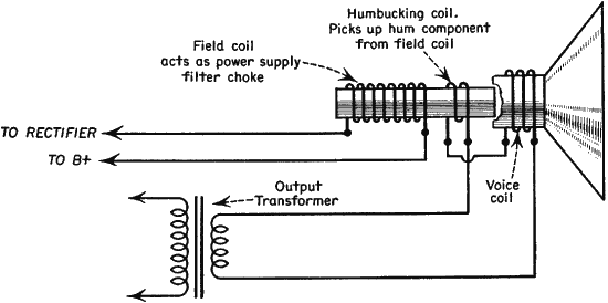
The hum in the field coil induces another hum in the humbucking coil which compensates the hum in the voice coil. An exploded view of a speaker with humbucking coil is shown in the next figure.

And here an example of a humbucking coil from a German thread.
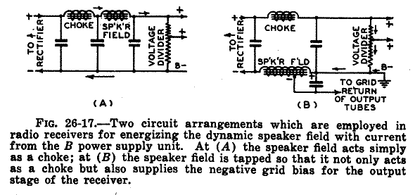
A third method uses tapped chokes. (Fig. 35) See also post #14

A fourth method is feddback hum to grid 1 of the output valve. (Fig. 36)

A fith method is a tapped output transformer. (Fig. 37) See also post #14

This last three methods are described in a German paper from 1947.
Regards,
Dietmar
To thank the Author because you find the post helpful or well done.
Rectifier data
Dear all,
I just wish to underline that the replacement of filter capacitors in old radio sets must be carefully evaluated and the use of a high-capacitance electrolytic cannot be considered the right solution to an annoying hum problem. I am sure that old radios could generate barely perceptible hum, if any, when they left the production lines of their manufacturers. All tricks were used by designers to reach this goal, as described by prof. Dietmar Rudolph with detailed photos, well illustrating how careful was their manufacture. Here is a hum-bucking winding circuit, as used in Phonola (Philips) 555/556 sets, around 1939.

The above diagram also shows the polarity of windings involved in the hum-canceling circuit. Since the hum cancellation effect derived from the algebraic sum of two opposite signals, this solution was polarity-sensitive, a single inversion resulting in a loud hum from the speaker.
We must assume that, with few exceptions, old radio original circuits operated properly with their specified components and no arbitrary change is required today to improve their performances.
Problems arises when some of the original components are no longer available and must be replaced with newer ones. Speaker coils, either the voice or the field ones, sometimes fail. When replacing an old dynamic speaker with a modern one, the filter section must be modified, replacing the inductor/field coil with a resistor. Even the value of the filter input capacitor must be increased in this case. But this replacement should be customized for each model and no general rules can be done.
Data given in the years by tube manufacturers for vacuum rectifiers are not homogeneous and show wide spreads, depending upon their working conditions. Design data of each radio set are unknown at all. The simple DC resistance of supply transformer windings varies from model to model and anyway is just a fraction of the total impedance that limits peak currents through the rectifier. More, due to the wide tolerance of electrolytic capacitors, typically around -20 to +50 %, a 33 uF can actually measure up to some 45 uF. Here are design data given for some vacuum rectifiers when used with capacitor-input filter:
| Tube type | Mfr. Data | Cap. Value | Peak-Current Limiting Impedance |
| 5R4 | RCA | 4 uF typ | 125 to 575 ohms min per plate |
| 5T4 | RCA | 40 uF max | 150 ohms min per plate |
| 5U4 | Brimar | 32 uF max | 75 ohms min per plate |
| 5V4 | Brimar | 32 uF max | 100 ohms min per plate |
| 5W4 | RCA | 4 uF typ | 50 ohms min per plate |
| 5Y3 | RCA | 10 uF typ | 50 to 140 ohms per plate |
| 5Z4 | Brimar | 32 uF max | 30 ohms min per plate |
| AZ1 | Philips | 16 uF typ | 100 to 800 ohms per plate |
| AZ4 | Philips | 16 uF typ | 100 to 800 ohms per plate |
| AZ11 | Telefunken | 16 uF typ | 100 to 800 ohms per plate |
From the above table, we can easily understand why a careful evaluation of the actual circuit is usually required, to stay within the proper limits specified for a given rectifier tube.
Regards,
Emilio
To thank the Author because you find the post helpful or well done.
Another hum compensation methods
In "Ghirardi, A. A.: Modern Radio Servicing, Murray Hill, 1935" another hum reduction method is presented, called shading ring. This shading ring is a short cut winding at the top end of the field coil. It may be found in early electro dynamic loudspeakers.


Additionally, hum also may be reduced if an extra choke is used, a luxory which in later times has been omitted.
Regards
Dietmar
To thank the Author because you find the post helpful or well done.
Eliminating the Hum in 1930
This has been a good review of hum reduction techniques.
The reference to tapped filter chokes reminded me of the article "Eliminating the Hum" by Benjamin F. Meissner from Radio News magazine April 1930. The article makes reference to "B-C" power supplies or battery eliminators. This refers to B-battery for the plate voltage and C-battery for grid bias.
More on peak current stresses:
The average current that is drawn by the set, for example 50mA, is supplied entirely during the current peaks by the power rectifier. Full wave rectifiers cut the peak currents in half because they conduct twice as often. But the peak currents can still be 5 to 10 times higher with a heavy capacitor load as the rectifier only counducts 20% or 10% of the time respectively.
In the case of vacuum tube rectifiers, peak currents are nearly universally specified because the effect of exceeding peak currents is to greatly reduce the thickness of the space charge layer that protects the delicate cathode coating from residual gas ion bombardment. As the tube ages and emission drops, it becomes easier to deplete the space charge with peak currents and, in the extreme, a change from space charge limited emission to thermally limited emission occurs. There is no protective space charge layer under thermally limited emission and damage to the cathode coating occurs rapidly.
In the case of series heater string sets, the AC source impedance is zero so that the peak currents are determined by the rectifier impedance, the capacitor size and any additional series resistor which is often present. In this particular case, it is easy to double the peak currents with much larger filter capacitors.
In the case of High voltage selenium rectifier bridges, which consist of long series stacks of low voltage selenium diodes, there is a lot of heat dissipated from the net high series drop. In German radios, these bridges are often mounted to the chassis for heat dissipation. This forward drop causes heat dissipatioin and an increase in temperature with higher peak currents. If the rectifier is already running pretty hot, it is unadvisable to heat it further with the higher peak currents of a much larger filter capacitor. A much larger filter capacitor is one that greatly reduces the ripple at the selenium rectifier from say 25Vp-p on a 250VDC output to only 5Vp-p. In this case the average DC current would go up a few percent with the larger cap, but the peak currents that determine heat dissipation could double. It would take some direct experimentation to verify the actual peak current increases with larger capacitors because of the relatively high forward non-linear impedance of high voltage selenium rectifiers.
A further effect of much higher peak currents is an increase in the heat dissipated in the primary and high voltage secondary windings of transformer powered sets. The transformer winding temperature can be estimated by measuring the winding resistance cold, and then right after a long period of play. The ratio of these two resistance readings is directly proportional to absolute temperature in degrees Kelvin. The most convenient winding to measure is the primary, which can be measured right at the power plug. The following formula estimates winding temperature with Thot and Tcold in degrees Celcius.
Thot=(Tcold+273oC)*Rhot/Rcold-273oC.
Increasing the size of the first filter cap may be OK, but some measurements and precautions should be taken.
More on tapped audio power transformer:
When a tapped audio power transformer is used to cancel hum that is dropped across the finite power pentode plate impedance, even a very modest cancellation of only 50% from a poor match between the load resistor on the short end of the tap and the plate impedance on the far end of the tap, still makes it possible to cut the size of the electrolytic cap in half, while retaining the same hum level as a non tapped transformer. In practical cases, a match of 30% is reasonable to expect between plate impedance and compensation resistor for a 10dB hum reduction with the tap trick. This gives some margin for saving half the capacitor size. More details on the nature of the cancellation are explored in Pentode Plate Hum.
Regards,
-Joe
To thank the Author because you find the post helpful or well done.
Rectifier peak current versus filter input capacitor
One of the topics discussed in the previous posts concerns the increase of the peak current in the rectifier caused by an increase in the value of the filter input capacitor (Emilio Ciardiello) and its negative effects on the life of the rectifier (Joe Sousa). While all of us agree that changing the values of some components cannot be considered as a good restoring practice, it has also been outlined that an increase in the value of the input capacitor plays only a minor role in this game because the peak current is mainly influenced by the resistance of the transformer windings (Paul Reid). While the ripple can be easily visualized and measured, the current in the rectifier can be visualized and measured only by modifying the circuit (inserting a resistor); moreover, making a meaningful number of tests is time-consuming. For these reasons I have prefered the use of a simulation to analyze these influences. The simulation is based on the equivalent circuit reported in Figure 1.

Figure 1- Equivalent circuit used in the simulations
The values of the components make reference to the SH 37WLK because this receiver was at hand for evaluating the correctness of the results. N.L. is an algebraic block describing the nonlinear link between voltage and current in the rectifier (a third order polynomial model has been constructed for the RGN1064/1805 using Least Squares), RT denotes the transformer winding resistance (440 ohm), LF the field coil inductance (20 H), RF its resistance (1650 ohm).The value of C2 is 4 uF and RL = 8250 ohm draws the same current as the considered set (of course the current absorbed by a receiver is not a linear function of the applied voltage but, for the purpose of this simulation, a linearized load does not introduce drawbacks). The considered values for C1 are 4, 8, 16, 32 and 64 uF in order to evaluate the influence of values much larger than the original one (4 uF). The linear part of the circuit has been described by means of an order 3 discrete-time state-space model with a sampling interval of 10 us. The simulation environment has been Matlab. Figure 2 shows the current across the rectifier for the considered values of C1; it can be observed that the variation of C1 has a very modest effect on the peak value that varies only from 169 mA to 170 mA when C1 is increased from 4 to 64 uF.

Figure 2 – Current IR in the rectifier (RT = 440 ohm)
A much larger effect can be observed on the ripple on C1, shown in Figure 3, and on the current in the field coil (Figure 4).

Figure 3 – Ripple on C1 (RT = 440 ohm)

Figure 4 – Field coil current IF (RT = 440 ohm)
The values that have been found for C1 = 4 uF agree very well with those observed on the SH 37WLK (Figure 5).

Figure 5 – Observed voltage on C1 (RT = 440 ohms)
The simulations have been repeated by considering a value of the transformer winding resistance equal to 1/10 of the real value, i.e. 44 ohm instead of 440 ohm. The results are reported in the Figures 6, 7 and 8.

Figure 6 – Current IR in the rectifier (RT = 44 ohm)

Figure 7 – Ripple on C1 (RT = 44 ohm)

Figure 8 – Field coil current IF (RT = 44 ohm)
In this case the peak current shows a remarkable increase but, again, is influenced only in a limited way by the variations of C1 (from 363 mA to 389 mA). It is thus possible to conclude that also large variations in the value of the filter input capacitor do not influence significantly the peak current through the rectifier; a much larger influence is played by the circuit resistance.
Regards,
Roberto
To thank the Author because you find the post helpful or well done.
Thread not linked to the model
The HV secondary winding resistance for any given transformer depends upon several parameters defined by the designer and including core material and size, flux density, turns and wire gauge of the windings themselves. The same position of the secondary windings, close to the core or external, greatly influences the diameter of their turns and hence their overall resistance values. We can assume that a given radio was so designed that windings, rectifiers, capacitors and everything else worked properly all together. From the above simulation we learn that the HV secondary windings in the transformer of the Siemens SH 37WLK measure 440+440 ohms: a quite high value indeed. This value is just in the middle of the resistance range specified for the rectifier, 100 to 800 ohms, and anyway high enough to limit peak currents.
But the simulation based upon the above example by no way can be applied to different models or sets. I just checked the secondary winding resistance of three power transformers on hand, reading values between 20 and 50 ohms. Then I ran Spice simulations on a simple full-wave rectifier feeding the load resistor and a capacitor, either 4 uF or 47 uF, trying 440, 50 and 20 ohms limiting resistor. The peak current increase with the higher capacitance value was respectively 8%, 22% and of 51%. I hesitate to define negligible a 50% increase over the design values! What is worst is that even a 50 ohms winding shall require an additional current limiting resistor if, say, one uses a 32 uF cap with 5R4 or a 5V4, according to the tube manufacturer’s datasheets.
And we are back to the beginning. I had no remarks at all on the supposed value increase of the filter capacitor, if this thread was correctly linked to the specific SH 37WLK model. But a generic repairing thread, as this was entered, could lead some readers to the conclusion that a hum problem can be anyway fixed by a careless increase of the filter capacitor. More, somebody can argue that, since a 33 uF capacitor reduces the hum, a 470 uF snap-in works even better. And this is exactly the wrong conclusion, even considering that in this case hum derived from a cable inversion.
Thanks to professor Rudolph, we now also know that probably the alternate non-polarized Siemens speaker for this specific Siemens model was fitted with a ‘shading-ring’ to prevent hum from the field coil.
Regards, Emilio
To thank the Author because you find the post helpful or well done.
Simulations
I can well agree with Emilio that the information that can be deduced from a simulation concerns only the system that has been considered; as a researcher in the field of dynamic models, I would also add that every model constitutes only an approximation, sometimes crude, of the complexity of the real system that it should describe. Despite these limitations, simulations can be very helpful in understanding physical phenomena; in the specific case they simply underline that the current variations due to the resistance of the circuit play a primary role, those due to variations in the input capacitance of the filter, a less important one, nothing else. Of course the entity of these variations is linked to a variety of factors, some of them not even considered in the two simple exercises that I had proposed. Increasing the value of the filter input capacitor for reducing hum remains, in my opinion, a practice to be avoided even in the cases when it does not lead to dangers.
The information on the loudspeakers endowed with a hum-bucking coil given by my colleague Dietmar Rudolph is very interesting. Professor Rudolph is a great expert of the SH 37WLK (see his many posts on the peculiarities of the SH 37WLK in the page concerning this receiver) and his help during the troublesome restoration of my set has been determinant. Professor Rudolph does not suggest, in his post, that the alternate loudspeaker designed by Siemens for the 37WLK is endowed with a hum-bucking coil. This, in fact, is not the case as can be seen in the next picture that shows a disassembled unit of this type, constructed on September 24, 1934.

Alternate Siemens louspeaker for the SH 37WLK
Regards,
Roberto
To thank the Author because you find the post helpful or well done.