Ballast tubes: solid state replacements
Ballast tubes: solid state replacements

In the past for a couple of friends I had to solve the problem of replacements for missing or damaged ballast tubes. These tubes were frequently used to stabilize current drained by loads, tube heaters or even entire radio sets, when considerable variations in supply voltage were expected, as in battery operated equipment. Many types were made, virtually for every applications, differing from each other for technology, size, nominal operating voltage range and current, base and power dissipation.
Today it can be difficult to find exact replacements. The greatest difficulty arises from the lack of complete information on the ballast to be replaced. Anyway when original types are no longer available, it is quite easy to build solid state assemblies that approach the behavior of these tubes, but for some waveform distortion when used in AC power supplies. Due to the variety of types made, it is impossible to give a single, well defined solution. The following notes show some basic circuits suited for AC/DC operation at different power ratings and give the guidelines for dimensioning their components.
- Preliminary safety and power considerations
A ballast replacement is a simple current generator, but circuit solutions and components must be carefully selected for reliable operation. The first step is the evaluation of the total power to dissipate. A filamentary ballast became very hot when operating and its solid state replacement has to dissipate more or less the same power. For safe operation, the replacement must be designed to dissipate the generated heat and to withstand common failures in the load, as short circuits. It should even prevent damages to the load as consequence of its own failures.
Excessive heat adversely affects the otherwise reliable operation of such a simple circuit, based on very few components. Harmful temperatures can easily be reached, since the solid state replacement is to be mounted inside a cabinet with poor air flow and close to other heat sources. The power handling capability is then the most severe obstacle to face in the design. The following example explains how the power can be calculated.
--------------
Suppose that we must replace a ballast specified for a nominal current of 0.300 mA in a range from 40 to 60 volts. This means that, when connected in series with the load, a 40 to 60 volts drop can be expected across the ballast. Strictly speaking then the approximate maximum power in watts should be:
P = 60 * 0.300 = 18 watts
Anyway, if the supply voltage is 110V and a short takes place in the load, the full line voltage could be applied to the ballast. The power in faulty conditions then can rise to:
Pf = 110 * 0.300 = 33 watts
Taking into account a 10% line tolerance and roughly a 10% component tolerance, a worst case faulty power of about 40 watts can be expected.
-------------
The series power transistors must withstand the worst-case power without damages. In other words their junction temperature must not exceed 150ºC (or 175ºC depending upon the types). Once known the maximum power, the junction temperature can be calculated. Read in their data sheets or estimate the transistor and the heatsink thermal resistance values. The total thermal resistance is the sum of them both plus a small corrector for the insulating mica washer, if any. When using mica and thermal compound, we can assume an additional thermal resistance of 0.5 to 1ºC/W.
ThR_tot = ThR case + ThR_heatsink + 0.75
The total thermal resistance multiplied by the total power gives the junction temperature raising over the surrounding air.
Delta_T = Pf * ThR_tot
The junction temperature will be:
Tj = Tair + Delta_T
In most cases we can assume that the air temperature is around some 60ºC (45ºC external temperature plus some raising inside the cabinet due to heat sources).
To safely handle the expected maximum power, possible solutions are to be found among:
- A) Selecting the proper case of power transistor(s). Approximately 6ºC/W is the thermal resistance for a TO-126, 3ºC/W for a TO-220, 1 to 1.5ºC/W for a TO-3 or its plastic equivalent TOP-3; exact values can be found in the manufacturers data sheets.
- B) Using larger or more efficient heatsink. Radiators with thermal resistance from 3.5 down to less than 1ºC/W can easily be obtained.
- C) Sharing the total power among two or more packages, either mounted on separate radiators or on a common larger heatsink.
- D) Adding a thermal switch, a PTC or a thermal fuse on the radiator.
A good compromise is to dimension the heatsink for the maximum predictable operating power and then add a thermal fuse to shut-off the device in case of overtemperature due to load shorts or other failures.
- Simple ballast replacement
The circuit below shows the basic current generator that can be used to replace ballast tubes when power is not greater than about 20-25 watts.
 |
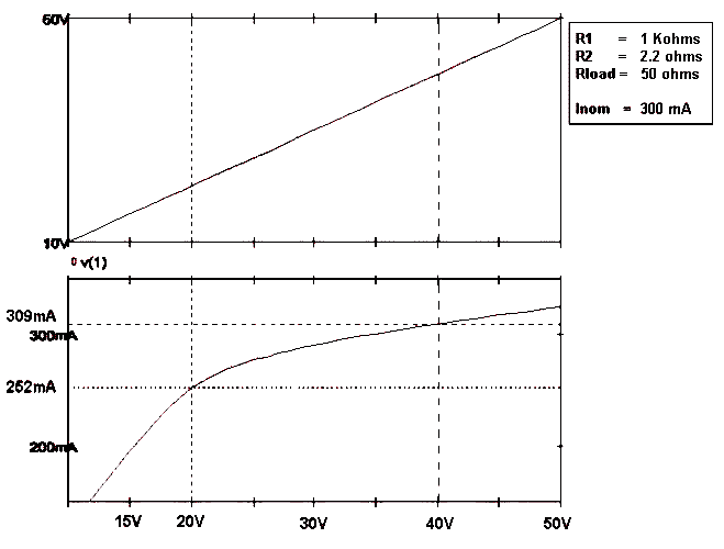 |
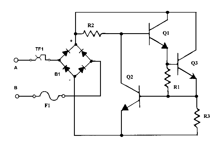
Fig. 1 – The schematic diagram of the simple transistorized AC/DC circuit. On the right, plot of the load current against supply voltage for 300 mA nominal design value.
Q1 should be selected for the highest possible Hfe, 20 or more, capable of withstanding the required voltage, current and power dissipation. Its base current could then be set somewhere between one fifteenth and one twentieth of the collector current. Q2 can be selected to withstand the base current of Q1. If Vmin and Vmax are the voltage limits and I, in amperes, is the nominal current of the ballast to be replaced, we have:
- R2 = 20 * Vmin / I ; select the nearest lower standard value. Check its power rating, Vmax*Imax: a power type, metal oxide or wirewound, is usually required.
- R1 = 0.6 / I ; select the nearest higher standard value
- F1 – select a type with current capability slightly higher than the design value
TF is an optional highly recommended thermal fuse or a bimetal switch mounted on the heatsink close to the power transistor Q1.
- Possible variants
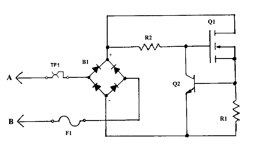
Some variants of the above circuit can be tried, depending upon specific applications. The circuit given in figure 2 below uses a N-channel power MOSFET instead of the power transistor. Its operation is very similar to that of the previous circuit. There is no base current in this case and R2 may be calculated for 1 milliamp or even less. It can be useful in medium to high voltage applications, when the shunt current derived by the base path of bipolar transistors appreciably deteriorates the regulation.
 |
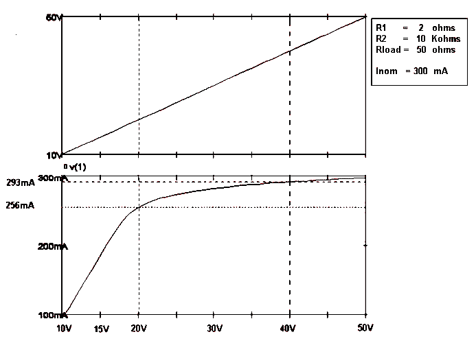 |
Fig. 2 – The diagram of the MOSFET circuit and the load current plot as function of input supply voltage. Note the better regulation in the range from 20 to 40V when compared with the previous bipolar version.
 |
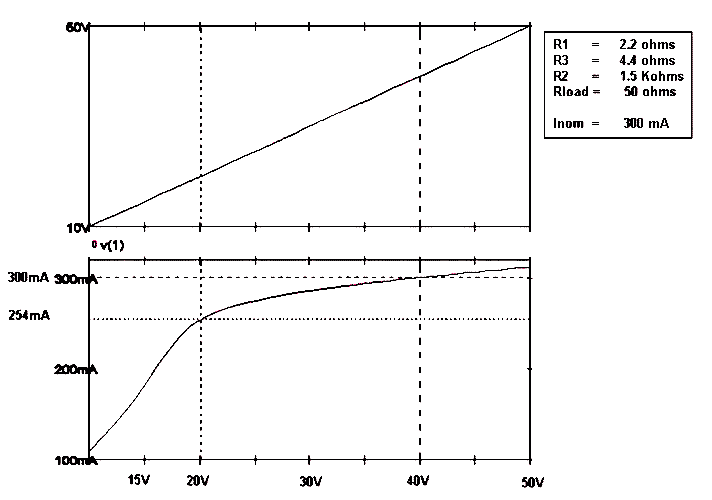 |
Figure 3 shows a regulator circuit suitable for high power operation. Here the total current is split between the two power transistors Q3 and Q1, connected in a quasi-Darlington configuration. This circuit is to prefer over the classic parallel connection with current balancing resistors because of its intrinsic gain. Half current will flow through Q3 when the drops on R3 and on R1 are both equal to about 0.6 volts. This is true when:
R3 = 2 * R1
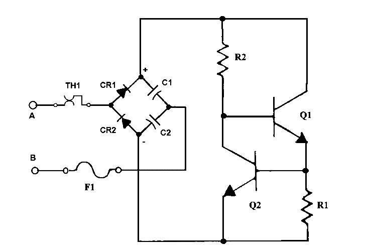
Fig. 4 – Zero dropout AC circuit
The circuit given in figure 4 can be useful at very low voltages, since it operates with zero dropout. It is similar to the first one described above, but uses a voltage doubler instead of the bridge rectifier. Part of the voltage generated by the doubler compensates the 1.8 approximate drop in the junctions, the exceeding overvoltage being just available across the current regulator. This circuit can only operate in AC.
To thank the Author because you find the post helpful or well done.
Transoceanic

In reading your article, the Zenith Transoceanic comes to mind.
When certain tubes start becoming rare, I personally have an issue of using them for daily use in a radio.
This is why I convert my radios to use 6E5C tubes instead of the EM34/35 tubes etc.
Your substitute for the balast tube, also makes the radio run better.
Thank you for your detailed explanation.
To thank the Author because you find the post helpful or well done.
Characteristics of replacements depend on temperature

Hello Emilio,
an electronical constant current source (or sink) is in principle a good method to substitute a ballast tube. But a problem could be the simple circuitry you proposed: It depends strong on temperature.
The controlling element of your circuitry is the transistor Q2 - more precisely the base emitter voltage of Q2. The base emitter voltage drop of a bipolar silicon transistor varies with -2mV/K (Kelvin). This means e.g. a voltage drop of .6Volts at 20°C decreases to .48Volts at 80°C. The curent of e.g. 300mA decreases to 240mA. This is an amount of 20%!
Everyone has to check if this is acceptable for its application!
I don't know a practicable solution to compensate the negative temperturare coefficient in a simple manner. And the simplicity is the high characteristic of your circuitry.
May be one could position the transistor Q2 on a cool area of the application!? An extension of the three wires of Q2 for this is no problem.
Regards, Hans-Jürgen Neuhaus
To thank the Author because you find the post helpful or well done.
Temperature drift
Dear Hans,
Many thanks for your remarks. You are absolutely right about the temperature drift. Anyway consider the following points.
By the way it is possible to design a precise current generator with virtually zero drift: it should require few more parts, a couple of diodes and a reference, but what is worst it requires an additional voltage drop of about 6.2 – 6.8V, the value of a zero coefficient voltage reference.
- Very few comprehensive data are available on ballast tubes. Anyway giving a look at the data of some Philips devices, as the 329 or the 340, you find a tolerance just on their on nominal value from 13 to 15%, in line with the drift figure you estimated. The accuracy of a ballast tube was also affected by surrounding temperature and cooling and by mounting position, even if I never found factory data on these items. Probably ballast tubes were handled by their manufacturers as lamp bulbs rather than as vacuum tubes.
- The transistor Q2 operates at quite low voltage and current levels. The collector current is in the order of one fifteenth and one twentieth of the controlled current and even less in the MOSFET or in the Darlnighton version. In most cases we are talking of 10 to 30 milliamps. At these currents Q2 has to dissipate a power lower than 40 milliwatts. A general purpose high-voltage TO-126 transistor, say the MJE340, has a thermal resistance of about 6ºC/W. This means that, with a small PCB heatsink for Q2 when needed, we can predict a worst case temperature increase in the order of 1ºC. The base-emitter voltage is then affected almost exclusively by the temperature of surrounding air, usually much lower than 80ºC.
- Anyway it is true that anyone has to check the application. I just gave some simple circuits and some hints to dimension their components. The actual design must be tailored to any possible combination of ballast type and application.
Regards, Emilio
To thank the Author because you find the post helpful or well done.
Simple improved variants
Simple current stabilizing circuits, suitable as ballast replacements and characterized by low temperature drift, can be readily designed when voltage peaks across the ballast do not exceed some 30-40V and power dissipation is quite low. In these cases popular three terminal voltage regulators can be used as current source, with several benefits. Here are some key features of such a solution:
- Cheap and readily available components
- The built-in voltage reference grants temperature coefficients in the order of 1mV/ºC or even better.
- Integrated voltage regulators contain built-in thermal overload protections.
The drawback is the low DC voltage that can be handled, 35 volts or less for most types or 60 volts for the LM317HV.
The circuits below show how to build solid state ballast replacements based upon three terminal ICs as current regulators. The given examples were designed to emulate the 3TF7, the ballast used in R-390 and R-390A communication receivers. The circuit can be readily adapted to other similar ballast tubes. Of course a good mechanical design is still required to build a true solid state replacement for the nine pin base 3TF7.
In the R-390 family the ballast is used in the heater supply circuit of the PTO and of the BFO oscillators, both 5749/6BA6W. The two heaters are series connected, requiring 12.6 V at 0.3 A nominal. The heaters supply is derived from a 25.2 V secondary winding of the power transformer. The 3TF7 provide the required voltage drop, also regulating the current flowing in the heaters. Specs of the 3TF7 and of its application can be summarized as follows:
- Nominal supply voltage: 25.2 VAC rms +/-10%, according to R-390A specs.
- Effective supply voltage range: 22.7 to 27.8 VAC rms
- Nominal heaters supply: 12.6 V at 300 milliamps
- Voltage drop across 3TF7: 8.6 to 16.6 VAC rms
- Stabilized current within 290 to 330 mA
Even if in normal operation the peak voltage across the ballast does not exceed 24 volts (the peak value of the maximum expected rms voltage), higher voltages can be found due to power distribution transients or even to accidental short circuits of the external load.
The first circuit uses a 7905/LM320T-5 negative voltage regulator as current generator. The reasons for this decision are the low dropout of the negative type, around 1 volt, and the quite favorable power distribution between the current set resistor, R1, and the regulator itself. Actually 1.5 watts (5 volts at 300 milliamps) are dissipated by R1, while IC1 should dissipate up to about 4.2 watts, depending upon the line voltage.
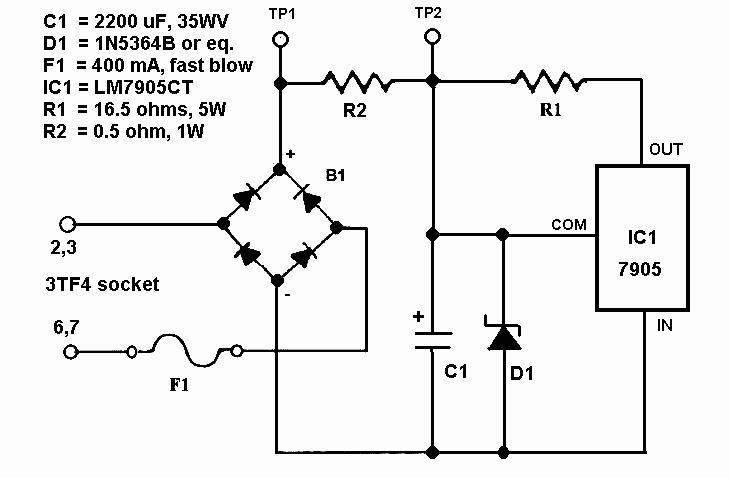
Fig. 1 – Schematic diagram of the basic current regulator.
 |
 |
Fig. 2 - The breadboard used to evaluate the performances of the current regulator as replacement of the 3TF7 ballast tube and the waveform across the load.
The current value is set assuming 5V across R1 and can be checked with a DC voltmeter across the same or across R2. The value of R1 is found dividing the stabilized voltage, 5 V, by the expected current, 0.3 A. Actual current values read on the breadboard are summarized as follows:
- At 47.8 ohms external load, the current remains at 302 milliamps from 28.0 Vrms down to some 23 Vrms, then drops to 282 mA at 22.0 Vrms. (Actually load should vary from 37.8 to 46.2 ohms, while minimum input voltage should not fall under 22.7 volts).
- At 42.7 (about the nominal value) and at 38 ohms load, current reading stay stable on 302 milliamps from 28.0 down to 22.0 Vrms supply voltage.
R1 can be easily obtained wiring two 33 ohms metal oxide or wirewound power resistors in parallel. Two 1 ohm metal oxide resistors were paralleled for R2. D1 was added to protect IC1 against line transients and in case of load short circuit. R2 limits the surge current through the zener, while F1 opens the circuit in case of steady overload conditions.
An even simpler circuit can be tried if a true rms voltmeter is available. The bulky filter capacitor C1 can be replaced by a simple 1 microfarad ceramic type, just to prevent oscillations.

Fig. 3 – Schematic diagram of the simplified circuit. The value given for R1 is approximate and for the best accuracy should be trimmed while checking the current by means of a true rms AC voltmeter across R2.
 |
 |
Fig. 4 – Breadboard of the simplified circuit and waveform across the load.
In AC operation the peak clipping action of the current limiting regulator causes some distortion of the sine wave, as shown in fig. 4. A moderate current variation with load and line variation, due to more or less pronounced clipping, can then be observed. A true RMS voltmeter, connected across the resistor R2, is required to measure the current flowing across the circuit and adjust the value of R1. The RMS current readings for several load values can be summarized as follows:
- At 47.8 ohms load, current increases from 274 to 296 milliamps changing the supply voltage from 22.0 to 28.8 VAC.
- At 42.7 ohms, current raises from 283 to 300 milliamps in the same supply range.
- At 38.0 ohms, readings from 289 to 305 milliamps were obtained in the above supply range.
From the above readings, for a given load, the current roughly remains within plus or minus 3% of the center value, for supply voltage variations greater than plus or minus 10% with respect to the nominal 25.2V supply. The current flowing in the circuit was calculated measuring the AC voltage drop across R2.
Other monolithic voltage regulators can be used in this application. The standard positive types, LM340T-5 or 7805 are not suitable in this specific example, due to their quite high voltage dropout. The variable type, LM317T, can be used with more or less similar performances. Its high voltage version, the LM317HVT, can also be used with improved survival capability against line transients. The diagram below shows how to use a variable 3-terminal voltage regulator.
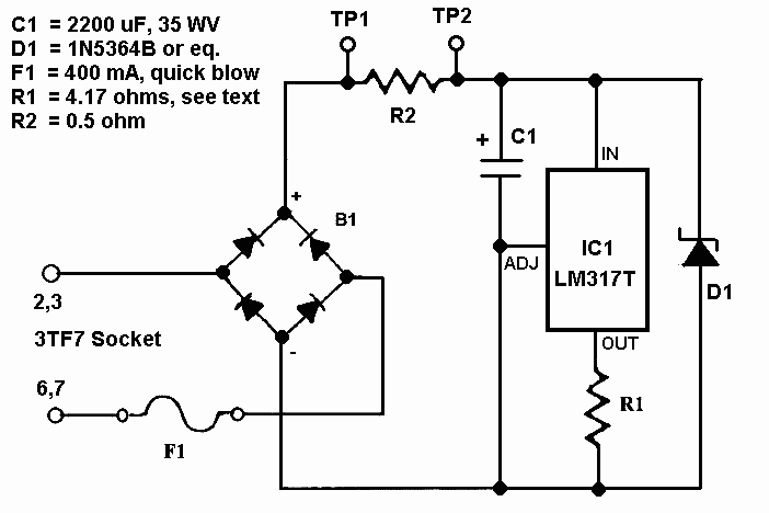
Fig. 5 – Current regulator using the LM317 adjustable VR.
Some notes about the component selection for this circuit. R1 must be calculated assuming a voltage of 1.25 volts. In the given example, the resulting value, 4.17 ohms, can be obtained paralleling one 4.7 ohms metal oxide or wirewound resistor, 2.5 W or more, with a small 39 ohms resistor. The power dissipated by LM317 in normal operating conditions could be as high as 6.8 watts and a proper heatsink is then required.
When using high voltage variants of LM317, the working voltage of C1 and the zener voltage of D1 can be varied according to the expected peak voltage.
To thank the Author because you find the post helpful or well done.
Another 3 terminal regulator option, TL783
Count of Thanks: 40
First, thank you all for this discussion! I first saw a ballast tube several years ago when a friend inherited a Zenith TransOceanic. Hi ballast was still working, but I remember thinking one could probably replace it with solid state equivalent if necessary, as it was unavailable. This is great!
Just wanted to say, for what it is worth, there is an even higher voltage 3 terminal regulator available in a TO-220 package, the TL783, which can handle up to 125V input-output differential. I just used one to replace a drifting zener regulator in my 1968 vintage Fisher 250T stereo receiver which has 60V input and 31V output.
Bill Gilbert
To thank the Author because you find the post helpful or well done.
Other alternatives
Some ballasts can be replace by custom wire, there is a wire sold on ebay for taking apart screens on phones and tablets suilable for home made resistors that have a useful thermal characteristic. I thought it might be nichrome, but resistivity and temperature coefficient seems wrong, it's slightly brassy colour, springy and very strong.
The other alternative can be a suitable wattage of halogen lamp, as these also have a current regulation characterisic. Finally, sometimes a pair of NTC and PTC thermistors (heating each other and insulated) to limit inrush and then regulate current can work.
When sets with ballast resistors where in production they were often used without additional resistors for 10V supply steps and mains supply was more variable too, so perhaps a full constant current source as good or better than iron wire in hydrogen isn't needed.
To thank the Author because you find the post helpful or well done.