CV150 Power Klystron, 1942
CV150 Power Klystron, 1942

‘The EMI team wisely decided to build their development model and get it operating in a coach at Hayes. They drove this coach with the klystron version of H2S to Hurn airport on 14 May.’. Sir Bernard Lowell in his "Echoes of War" so tells the short lived story of an obscure yet extremely advanced British achievement at the beginning of microwave airborne radars. It was the CV150 pulse power klystron, designed by the EMI team leaded by the pioneer Alan Blumlein for the T.R. 3539 radar transmitter of Oboe Mark IIB.
In the first half of 1941 early microwave airborne radar sets were designed for AI use aboard of night fighters and for ASV, to patrol Atlantic convoys. Terrain mapping by metric radio-localization sets, investigated years before by the same Bowen, barely allowed seeing coastal lines. In the second half of 1941, relying on the resolution of microwaves, new tests were made to use them in terrain guidance. It was decided to design a self-contained system to guide heavy aircraft of the Bomber Command over their targets in enemy territory. In November 1941 the very early H2S was ready: an AI Mk VII system modified with a fixed angle scanner returned echoes of the Southampton town from 5.000 ft. A variant, based upon a high-power pulsed klystron, was decided few days later. Such a variant had political rather than technical reasons, since magnetron was considered a vital secret to be carefully preserved. No authority was given to fly magnetron sets over continental Europe, fearing that its secret could fall in enemy hands. On the contrary, a set using a klystron transmitter would have revealed nothing new and its capture would have addressed Germany towards a predictable dead end. Birmingham had already investigated with poor results klystrons as power sources, until in the mid 1940 early GEC cavity magnetrons started delivering thousands kilowatts. On 23 December 1941 a contract was therefore placed with EMI Hayes to design the power klystron itself and to build fifty modified radar sets. Preliminary specifications of the system and of the klystron itself were presumably derived from those of the AI Mark VII. The CV38, the magnetron released shortly before, typically delivered 10 kW output pulses. EMI hastily built its PK150, registered as CV150, and prototypes of the entire system.
The images given by Lowell of a coach with strange antennas on the roof, running round the EMI plant, appear to be part of the deception that the British were preparing: a representation to fool possible German spies and confirm the use of the klystron as source of RF power.
First trials of the magnetron H2S on heavy bombers were made on the Halifax V9977 arrived at Hurn on 27 March 1942. A second Halifax, the R9490, arrived on 12 April 1942. This one was fitted with the EMI variant to run comparative tests. In chapter 13 Lowell tells of remarkable differences between the two sets. What Lowell does not say is that in March the H2S transmitter had been uprated, replacing the CV38 with the new strapped CV64. Still retaining the old modulator, the new magnetron fed the antenna with pulses exceeding 40 kW. Power would further increase to over than 100 kW when the new modulator with the CV125 trigatron was ready.
Unfortunately the entire EMI design staff and even the same magnetron prototype went lost on Sunday 7 June in the crash of the V9977 during a test flight. Deaths of Blumlein and of his team caused the subsequent cancellation of the program and any further developments of power klystrons were abandoned. Nevertheless the CV150, although at that time it was considered nothing more than an expendable toy, was another prime British achievement. Maybe it was too advanced for its time, anyway it can be seen as the forerunner of the many high power klystrons developed years later at Stanford and elsewhere.
Fig. 1 - Views of the CV150 pulse power klystron. Click to enlarge.
We must assume that in December 1941, when EMI started developing its PK150, its goal was a power output comparable with that of CV38: 10 kW typical output pulses at about 100 kW in input. From the TRE report T 1473 we learn that CV150 well exceeded that target:
- Peak input power 150 kW. 80 W maximum mean input power
- Peak output power 18 kW typical, up to 30 kW obtainable at lower duty
- Cathode voltage pulsed to -12.5 kV
- Peak collector current 6 amps
- Peak resonator current 6 amps
- Wavelength centered at 9.4 cm, adjustable plus or minus 2.5 mm
- RF pulse build-up in the order of 100 ns.
Waiting for the proper modulator, tests were arranged with a Type 64 modulator, modified for 4 µs pulse length. A special 1,5:1 step-up pulse transformer was added to raise voltage to 12.2 kV. The TRE report underlines that, taking into account the overall conditions of tests, results were consistent with expectations: 15.2 kW were measured in the water calorimeter at center frequency. CV150 then gave power enough to compete with the cavity magnetron. Looking at the high value of the resonator current, about one half of the cathode emission, the same device had evident margin for further power increases, with simple changes of grid shapes and some focusing of the electron beam. Unfortunately, after the project cancellation, the same klystron was shelved for the rest of the war. Attempts to use the CV150 in other applications, as in the ‘Lucero’ navigation system, never got beyond prototype phase.
Luckily, thanks to its unique design, the memory of such a device was frozen into the diary of Ed Ginzton, Professor in Physics at Stanford and cofounder of Varian. His notes, after a trip to Britain early in 1944, are reported in the historical background of the paper ‘HIGH-POWER KLYSTRONS: THEORY AND PRACTICE AT THE STANFORD LINEAR ACCELERATOR CENTER’ by George Caryotakis. Ginzton’s notes are today one of the few available sources of information about the tube and its performances.
“…I saw a klystron of a remarkably simple design which produced 20,000 watts of power, well beyond any klystron made in the United States at that time. The fact that it was so simple and so beautiful impressed me enormously, and led me to develop a still bigger tube a few years later.
A two resonator klystron, using grids, and operating 12,000 volts has been designed and built for 9.1 cm. It was intended for an airborne system but due to changing circumstances will probably not be used. It differs from other pulsed klystrons developed in Britain in that it uses a very large beam cross-section, a very large current density and grids to improve the modulation coefficient of the gaps. Although the grids are large in diameter, the RF losses in these are made small by using large grid spacing. The effect of the latter are made small by the high acceleration voltage. As such, this tube represents the furthest deviation from standard klystron design that I have ever seen. The cathode focusing and/or grid interception losses are poor.
Only 50% of the current passes through the short, stubby channel and one would think that this should be much better. But in spite of this, the overall-efficiency at 12kV, and 150 kW input is 20%. This means that the actual efficiency is about 40%, that being the highest efficiency for a klystron that I have ever heard of. The tube uses a slot for coupling. It has a waveguide output, and it is tunable by means of plungers over 5%. The starting time is not larger than 0.1 – 0.2 microseconds. The tube is small, light, very easy to make, is easily tunable and can be used as a power amplifier. It is this tube that makes me think that the klystron may yet rival the magnetrons.
The life of the tube seems to be about 250 hours at present. It is thought that Ba is being evaporated from the cathode which finally ruins the tube. Experiments are now being conducted with lower cathode temperatures and longer life is indicated. The tube is now in preproduction stages... ”
Ginzton also left drafts of the internal electrode arrangement and of the grid shape.
 |
 |
Fig. 2 - Left, sectional drawings of the klystron. Right, drafts left by Ginzton. Click on each image to enlarge
In 1948, few years after the war, Marvin Chodorow at Stanford posed near his latest achievement, the 30 MW klystron prototype MKIII, holding a sample of CV150 in his hands.

Fig. 3 - Marvin Chodorow at Stanford holding a sample of the CV150 near to the first 30 MW klystron prototype. Source: slac.stanford.edu/cgi-wrap/getdoc/slac-pub-10620.pdf
The diagram of the experimental klystron transmitter T.R. 3539 used in Oboe Mark IIB is given below. Full details, including the ancillary components, can be found in the TRE report T 1473
Fig. 4 - Diagram of the RF section of Oboe Mk IIB. Click to enlarge.
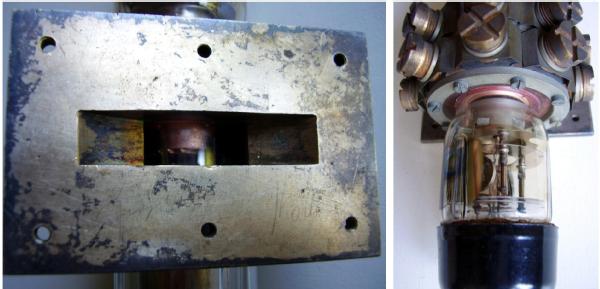
Fig. 5 - Left, the heavy and well-spaced rods of the second grid are visible from the output flange. Right, close-up view of the large cathode. Click on images to enlarge.
Probably the decision to cancel the project delayed for years the use of power klystrons. Luckily the same decision prevented the capture by enemy of a device which, looking at its post-war power increase, could have led to unpredictable consequences on the war. After all, despite daily bombardments and destructions, a warped CV64 sample found in the wreckage of the H2S no.6 captured near to Rotterdam led Germany in eighteen months or so to develop its own power magnetron technology, still unexplored before.
Bibliography:
- Echoes of War, by Sir Bernard Lowell
- Edward Ginzton Papers (SC0330). Department of Special Collections and University Archives, Stanford University Libraries, Stanford, Calif
- TRE report T1473
- German Multi-Cavity Magnetrons, by Emilio Ciardiello
Last edited by Emilio Ciardiello on 19 March 2020.
To thank the Author because you find the post helpful or well done.