grundig: 5040W/3D Circuitry Analysis - Part 3
grundig: 5040W/3D Circuitry Analysis - Part 3

(Translation of text originally by Thomas Günzel)

Here are links to Part_1 and Part_2.
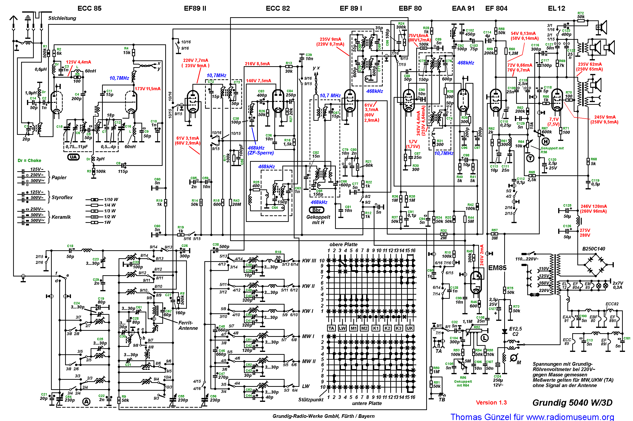
The complete schematic diagram v1.3 is here.
The FM IF Amplifier
Dear friends of the forum,
Now that we have had a detailed 2-part discussion of the FM tuner, we'll move on to the IF amplifier.
See this diagram for my first question:
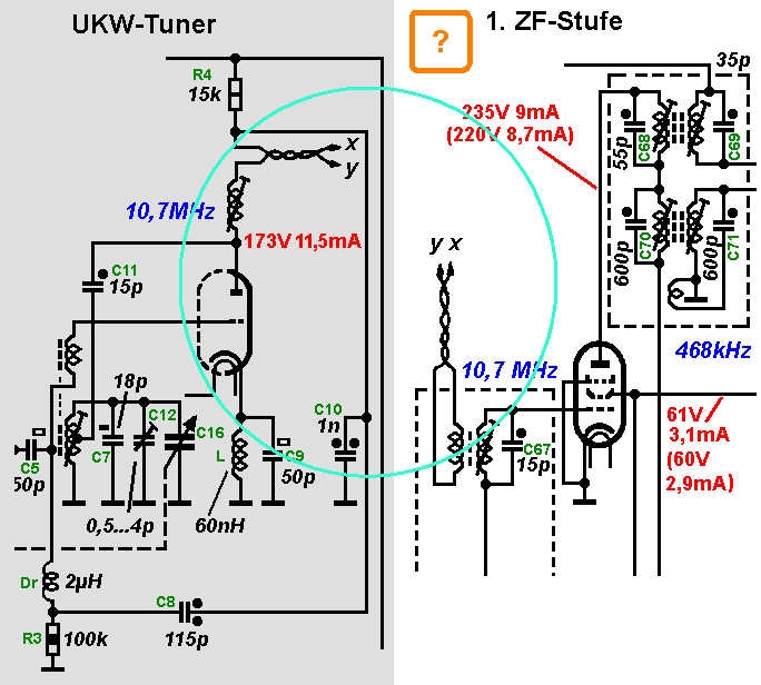
Circuitry:
Why was the connection from the FM tuner to the first IF stage made with a twisted pair?
On the primary winding of the first IF transformer there is no capacitor. Does that mean it has only one tuned circuit, and the primary coil is just an inductive coupling?
Production:
Before final assembly, the FM tuner had previously been aligned!
The routing of the twisted pair couldn't be done exactly the same every time. Was it necessary after assembly of the complete set to readjust the coil in the tuner (at the anode of the second section of the ECC85), or was it sufficient to simply adjust the first IF transformer?
I'm looking forward to lively participation. Whoever doesn't have access to post in this forum is welcome to send me (Thomas G. or Tom A.) questions by email.
Thomas G.
[To send an email to me (Tom A.), click on "mail to the author" at the bottom of this thread. To send an email to Thomas G., go the the German_thread and click on "mail to the author" at the bottom of the first post.]
To thank the Author because you find the post helpful or well done.
A frist attempt to explain
(Translation of text originally by Dieter Barkawitz)

It looks like no one has enough confidence in his answer to reply. Then I'll start things off, at the risk of writing something incorrect.
On question 1:
The twisted pair transmission line between the FM tuner and the first IF stage is twisted so that it can serve as a balanced (symmetric) transmission line with nearly constant impedance. The characteristic impedance is determined by the diameter of both wires and their distance from one another (in this case, the thickness of the insulation times two).
On question 2:
The first IF transformer, which has only one adjustable ferrite core, I would assume has its primary and secondary winding tightly coupled, so that the primary capacitance is transformed to the secondary. The primary winding is necessary in order to couple the balanced feed line (the twisted pair) to the unbalanced grid circuit of the first IF stage. Therefore a transformer with a single tuned circuit and a coupling coil is used.
On question 3:
Given that the FM tuner was previously aligned, no additional readjustment of the output circuit of the ECC85 in the tuner is necessary after final assembly. For the previous alignment of the tuner, it would be sufficient to terminate the end of the twisted pair with a resistor matching the characteristic impedance of the transmission line.
To thank the Author because you find the post helpful or well done.
Evaluation
(Translation of text originally by Hans M. Knoll)

Hello Herr Barkawitz,
Here is my answer:
Your answers 1 and 2 are recognized as logical conclusions and therefore correct.
UPDATE: I added some details in post 7 with measured values of parallel wire transmission lines.
Regarding your answer 3:
Your answer is also accepted. As can be seen in the following text, it's a matter of how you see things with respect to the question: Since it was previously aligned, does get get aligned again or not?
Figure 307
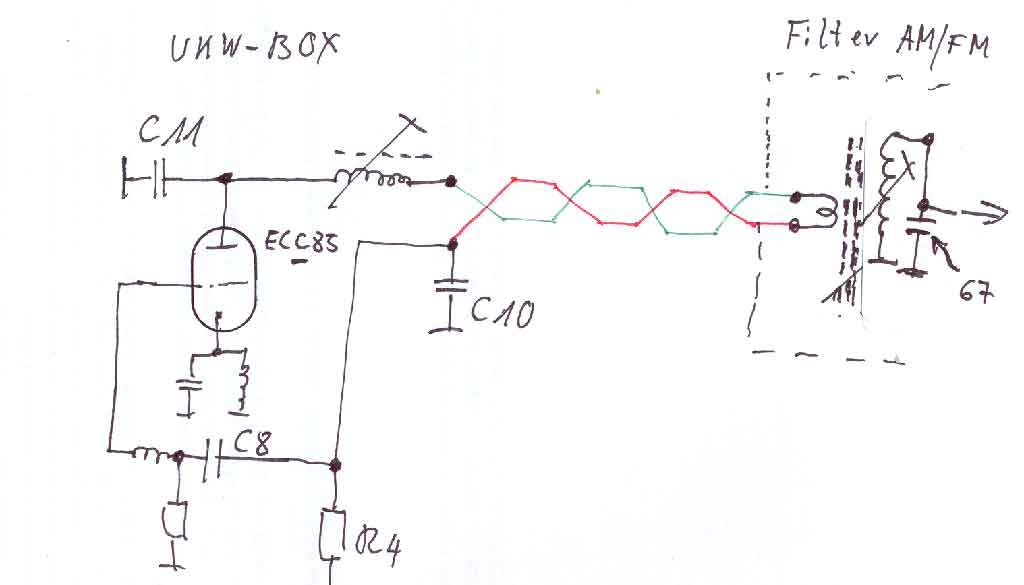
As can be seen in this sketch, the link and the coupling coil are part of the inductance of the circuit.
The inductance of the coupling coil, however, is affected by the position of the adjustable core in the IF transformer, and the position of the core in turn depends on the capacitance of C67, the wiring, and the next tube. For top-notch performance, a final adjustment of the coil in the FM tuner box is necessary, and was actually done.
Greetings,
Hans M. Knoll
To thank the Author because you find the post helpful or well done.
(Translation of text originally by Dieter Barkawitz)
Hello Herr Knoll,
It's very nice, and an honor for me, that you could agree with many of my answers!
As you have shown, the feedline to the first IF transformer and the coupling coil in series with it form part of the inductance of the anode circuit of the ECC85.
If the first IF transformer is tuned to resonance it becomes a purely ohmic impedance (a pure resistance), and as a result, this is true of the coupling coil too. Therefore the feedline is terminated with a matched resistive load. Therefore, the termination resistance, which is created by the coupling coil and which matches the characteristic impedance of the transmission line means that there will be no relectinos on the twisted pair. In this case, the feedline simply looks like its characteristic impedance, and this R is in series with the anode coil of the ECC85. If all of this is correct, then the twisted pair simply affects the Q of the anode circuit and increases its bandwidth.
Of course it's clear to me, that for a high quality product, the tuner would be adjusted as part of a final alignment. Therefore I didn't understand the question by Herr Günzel.
Regards, Dieter B.
To thank the Author because you find the post helpful or well done.
(Translation of text originally by Andreas Steinmetz)

Hello Herr Barkawitz,
Sorry, but I've got a different opinion. Let's discuss it:
Only the parallel circuit as a whole becomes ohmic at resonance. Each of its components continues to behave as a capacitance or a (damped) inductance. In particular, a rather large reactive current flows between the C and L, because of the increased voltage at resonance. Therefore I view the complete combination of the transmission line and coupling coil as an inductance, which together with the adjustable main inductor at the anode forms the total inductance of the resonant circuit. Since the wavelength is long compared to the length of the twisted pair, in my opinion it is not necessary to take the characteristic impedance of the line into account. The overall inductance is certainly damped, but only because of internal damping and radiation, which is kept small by the use of a twisted pair. Not because of any assumed characteristic impedance of the line. I don't have the set in front of me, but the coupling coil is probably not very big, and therefore its influence overall is not so great...
Andreas
P.S.: Rough calculation: Assume that the transmission line is physically 15 cm long (I don't know the exact length). The electrical length, taking into account the reduction factor of 2/3, is only 1/1000 wavelength. At 10.7 MHz the wavelength is around 30 m. Therefore the coupling inductance is hardly affected by the transmission line. The inductance is about the same at the input of the line as it would be directly at the coupling coil. That even applies if one allows for some capacitance (estimated to be a few pF). Regarding losses via internal damping and radiation, see above,
To thank the Author because you find the post helpful or well done.
My answers to Thomas G.'s questions
(Translation of text originally by Hans M. Knoll)
5040W/3D part 3
Question 1(a):
I could make it very simple for myself and say: a shielded cable is more expensive. However, that would only be a partial answer. In addition, "twisted pairs" are commonly as "link couplers" by radio amateurs since they are easy to use.
Update:
To shed some light on the question of "twisted pairs", made some measurements using the materials and equipment I have, and calculated the characteristic impedance of three versions of parallel wire transmission lines.
The result surprised me a little. I thought there would be more difference between parallel and twisted pairs.
Here are the results: Z for each = 259 ohms, 175 ohms, and 166 ohms (calculated).
Figure 309
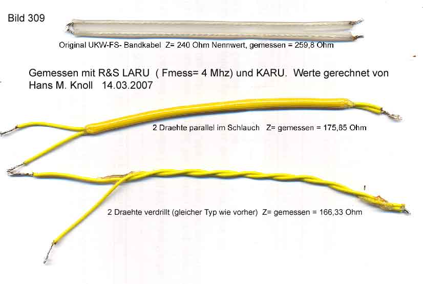
Figure 301

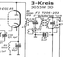
Possible answer: We can't tell anymore why a second IF coil was not used in the box, as discussed in Part 2 post 7. See Figure 302.
Figure 302

In the first IF filter, on the chassis, to which the twisted pair is connected, there is room for another coil. It would therefore be possible, that between the FM-box and the first EF89, a three circuit filter had been planned. A year later in the 3055, 4055, and later in the 6098 or 6099 that was the rule.
The output coupling would have been there, according to Figure 303, simply to make sure that only 10.7 MHz would be present (since the second circuit, with its 40 pF at the top of the coil, works as a low pass filter), and to minimize the wiring (switching). That happens first at the 3rd circuit.
Figure 303
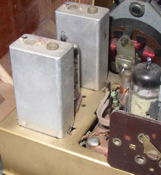
Now for the real question:
If you look at the assembly, where the components of the FM box are connected to the 1st IF transformer, you can see that there isn't much distance to span. For mass production, a shielded cable would have to be stripped back about 15 mm on each end so that the connections could be soldered. That would mean a cable that's shielded for about 45 mm and unshielded for 2 x 15 mm. In addition, if you look at the circuit, you can see that if it were a normal shielded cable, the shield wouldn't be connected to the chassis, but instead to C8.
That could only be avoided by using a small coupling coil. To see why using a shielded cable would not be usable, see Part 2 post 7: At the upper connection of the first IF coil = C11 there is the oscillator voltage with an amplitude of more than a volt.
Repeat Part 2 post 7:
(In addition, radiation of interference had to be reduced especially in FS-zone III. Therefore the inductive coupling of the IF and oscillator couldn't continue to be used. Any coupling winding with a small number of turns on each IF coil unfortunately has a harmful resonance, which could escape via harmful signals on the IF wiring.)
[At 100 MHz, the smallest capacitances to the outside produce chassis radiation due to currents, since the sheet metal functions like an antenna. Starting in 1953, such radiation in the free field had to have a field strength of less than 150 uV/m for the fundamental, and 30 uV/m for all harmonics at a distance of 30 meters.]
A twisted pair of wires are don't allow much magnetic leakage, because the polarity alternates along the wires.
Figure 304

Figure 307
.jpg)
What would magnetically couple to this?
It is known that any current, caused by capacitance, and flowing out of voltage generating points on the chassis, also creates a magnetic field. In addition there is the magnetic radiation from the IF transformers, especially from the ratio detector where the IF voltage is highest. There were good reasons why Loewa-Opta and Telefunken already developed solutions in 1952, in which the whole circuit including the EB41 or EABC80 tube was integrated into a filter can, as was later done with semiconductor diodes.
Figure 305
Figure 306
It's clear to me, that you cannot easily imagine, if you've never built and aligned a radio. These magnetic fields wander around in the sheet metal of the chassis and also show up at our twisted pair. The IF signal level at this point is only in the microvolt range.
There are good reasons why FM boxes are often grounded at only one point, so that chassis current can't flow through the box.
With the tight spiral of a twisted pair, the penetration of field lines is greatly reduced. The wires are self-shielding; the cold wire shields the hot one.
A shielded cable has a surface which is exposed if it's not soldered to ground. For the reasons discussed above (no output coupling coil, and C8 as reference point), the shield couldn't be grounded. Therefore a shielded cable isn't a good of a choice as a twisted pair with its small surface area.
Question 1(b):
The winding to which the twisted pair is connected is just a small coupling coil (typically 2 turns) wound directly on the secondary coil and it is affected by the magnetic field in the adjustable core. The entire anode current of the ECC85 flows through this coupling coil and is therefore strongly coupled to the secondary circuit. As can be seen on the schematic diagram, there is only one adjustable core and adjustment symbol in the winding.
Question about production:
Even though it had been previously aligned, the entire FM box was realigned with a wobbler after final assembly. When all stages are at their limits, the first filter determines the selectivity and is therefore very important.
Repeat: From post 4:
From this sketch you can see that the link and the coupling coil are part of the inductance of the circuit. The inductance of the coupling coil, however, is affected by the adjustment of the IF transformer, the position of the core as well as the capacitance of C67, the wiring, and the next tube. A final adjustment of the coil in the FM box is therefore necessary flor best performance and was actually done.
The high frequency circuits were aligned with a calibration tone, using an output meter and with headphones.
The End.
To thank the Author because you find the post helpful or well done.
Question 2 on the FM IF amplifier
(Translation of text originally by Thomas Günzel)
First, let me say "thank you" to Herr Barkawitz and Andreas Steinmetz for their technical contributions.
A hearty commendation to Hans, who once again has put an incredible amount of effort into answering the question with detailed pictures, sketches, and background information. Thanks!
Now for the second question:
I have pulled together the relevant circuitry details in the diagram below.
For a larger view, simply click on the picture!

Question 2:
What is the purpose of the combination R24//C86 and "feedback" via R1 to the grid of the FM RF stage?
I'm curious what your answers will be!
Thomas G.
To thank the Author because you find the post helpful or well done.
An attempt to explain
(Translation of text originally by Georg Beckmann)

During the positive half of the cycle grid current flows in the EF89 II. This causes a negative charge on C86. The higher the amplitude of the IF signal, the greater the negative voltage, which then regulates the gain of the RF stage. Now I've got a terminology problem, since naturally this doesn't happen in sequence, but rather the IF signal level is held more or less constant by this mechanism. As far as its output is concerned, EF89 II operates in class C, that is, the amplitude is limited (it functions as a limiter). For the case of FM modulation, any remaining amplitude modulation should be minimized. The desired information is in the frequency modulation; any amplitude modulation is mainly interference.
To thank the Author because you find the post helpful or well done.
(Translation of text originally by Dieter Barkawitz)
First I'd like to thank Herr Knoll for his clear explanation and, as always, his detailed description!
A question about the measurement of the characteristic impedance of the three test transmission lines: I've also made these kinds of measurements, but with much longer cables and, above all, significantly higher measurement frequency and the use of a directional coupler. If one varies the termination resistance, the characteristic impedance can be determined by observing when zero reflected wave occurs.
You wrote that the measurement frequency was 4 MHz. How could a usable measurement be done with such an extremely short test cable compared to the wavelength?
For question 1(b) you wrote:
"The winding attached to the twisted pair is just a small coupling coil (typically 2 turns) wrapped directly on the secondary coil and coupled to the magnetic field of the adjustable core. The entire anode current of the ECC85 flows through this coupling coil to create a tight coupling with the secondary circuit. In the schematic diagram one can see that there is only one adjustable core and one adjustment symbol in the winding."
I see it exactly the same way. However, if that is correct, then it should also be true that the signal feeding the resonant circuit should be in phase with the voltage in the resonant circuit. In other words, the driving signal is real, with no imaginary component. The imaginary component would be eliminated by its coupling through the transformer to the secondary, and the secondary would no longer be in resonance. And that's exactly the condition that allows the twisted pair to be truly RF-shielded and prevents spurious feedback from the output of the ratio detector back to the input of the IF stage.
What is the purpose of R24/C86 and the feedback...?
Herr Beckmann already explained this very nicely with a rectification effect via grid current. It should be mentioned at this point that the voltage on the hot end of R24 is negative because the grid of the tube, viewed from ground, is on the other side of the voltage source, and therefore the polarity is reversed. Capacitor C86 serves simply as a storage capacitor to maintain the voltage during the negative half cycles of the resonance signal; therefore its capacitance is not very critical. It is also worth noting that in this simple manner, two tubes are regulated -- both the EF89 II and the ECC85 I.
The operating point of both tubes, under quiescent conditions, is in the class A regime, and moves in the direction of class B with increasing signal amplitude. In my view, even with very strong input signal strength, class C operation does not occur, since there would have to be 10s of uA of grid current flowing at the EF89. Suppressing amplitude modulation by means of class C operation is the job of the EBF80 in the next stage, which, by the way, uses a similar self-regulation with R17 and C58.
Regards, Dieter B.
To thank the Author because you find the post helpful or well done.
(Translation of text originally by Dieter Barkawitz)
Now I'd like to go discuss what Herr Steinmetz wrote.
A quote as a reminder:
"Only when considered as a whole unit does the parallel resonant circuit become ohmic at resonance. Each of its components continues to behave as a capacitance or a (damped) inductance. In particular, because of the increased voltage at resonance, a pretty large reactive current flows between C and L.
In this way I view the overall combination of the transmission line and coupling coil as an inductance..."
Naturally you're correct when you write that a resonant circuit is only real (i.e., ohmic) from an external point of view, and internal to the parallel circuit, 180° phase-delayed currents flow through L and C. However, if this resonant circuit is constructed as a transformer with an additional coupling coil, then any change in the loading of the coupling coil, whether ohmic or not, will be transformed, either as an inductance or capacitance, depending on the square of the turns ratio (n1:n2)2. That holds in both directions -- either for coupling in or out. At resonance, the resistance which is responsible for the Q of the resonant circuit is transformed and appears as an ohmic impedance (i.e., pure resistance) at the coupling coil. The feed line, with its Z, is matched to this resistance.
Now, with regard to your update relating to the very, very short transmission line with respect to the wavelength:
In this case, the transmission line doesn't transform a signal; just the opposite is the case. It's a matter of getting the signal from one part of the circuit to another with the best possible RF shielding and a low cost. That can be done only with a matched transmission line in which the least amount of transformation occurs and it also helps that the transmission line is so short. For this reason, the output impedance of the entity generating the signal, the impedance of the transmission line, and the input impedance of the circuitry to which it is connected, are all matched. In addition, the amount of transformation that occurs in a very, very short, but poorly matched, transmission line should not be underestimated, since the transformation occurs outward from the null point following the sine curve of the standing wave. And since the slope of a sine wave is steepest as it passes through the null point, this is exactly where the biggest transformation effect occurs along the transmission line.
Regards, Dieter B.
To thank the Author because you find the post helpful or well done.
(Translation of text originally by Andreas Steinmetz)
Hello Herr Barkawitz,
Your comments sound logical to me. It's possible we're speaking past each other, or there may be some mistake. I'll think about this some more and post something here when I (hopefully) know more. Unfortunately I don't have the time for precise measurements, for example, of amplitude and phase at both ends of the twisted pair. Then we could really see what's happening.
Andreas
To thank the Author because you find the post helpful or well done.
An attempt to mediate
(Translation of text originally by Hans M. Knoll)
Hello Herr Barkawitz and Herr Steinmetz,
I'd like to intervene...
I have drawn two sketches -- Transformation 1 and 21, which are attached as pdf files for better quality.
The first (1) shows three circuits, Figs. 1-3. Fig. 1 is the one we are discussing. I gather that you would agree that in Fig. 1 it doesn't matter whether the 2-turn coupling coil, from a mechanical standpoint, is wound directly over the secondary, and from an electrical standpoint is in series with the primary circuit (as in the 5040), or alternatively, whether it is mechanically on the primary and electrically in series with the secondary. For "critical" coupling, which depends on a value of k/d = 1, the two scenarios are the same.
Does that make sense? If so, then all three circuits are functionally identical.
If I would first say: The step-down transformed resistance is 115 ohms at the output of both circuits only when the circuit is tuned (otherwise it is either damped or mistuned).
If the second circuit, with its output impedance of 115 ohms were connected to the first circuit (at its output), then the signal level at the connection point, as well as at the top end of both circuits, would fall by half or 50% compared to having no connection.
That is the meaning of "critical" coupling, or: coupling = k/d = 1 (where "k" is the coupling factor, "d" is the damping of the circuits for the case where "d" is the same for both, if the actual calculation is not done).
If you agree with the above, then we can go to sketch (21).
There, in the bottom section, is the case we just discussed. Each output has the 115 ohm impedance. If I now add a pi-network with Z = 115 ohms at input and output, between the 115 ohm feed points, "k" is of course changed, and thereby also k/d. As Herr Barkawitz said, I can say that the pi-network sees 115 ohms at both its input and output, the classic case of matched impedance.
What then? If I also do that in the upper sketch (the 5040W/3D circuit), what happens is as Herr Steinmetz said: The primary connection is not longer real, but instead only XL or inductive reactance.
The fact the the circuit now has a loss resistance of 115 ohms will now be plainly visible. Because there is no magnetic coupling between the coupling coil and circuit 2, the 115 ohms is not transformed with Ue squared; instead XL and R are added as vectors. The transformation rule (Ue squared, or turns ratio squared) does not apply.
The simulated "twisted pair" made from the pi-network Z = 115 ohms is no longer matched at its input, and no longer free of reflections, as Herr Barkawitz said or meant.
Let me ask you to ponder that and check it. We're going a bit too deep into the physics of tuned circuits -- much more than intended. We wanted to explain circuitry methods. Impedance matching is certainly part of that, but I hope you can accept the explanation above.
Best regards, Hans M. Knoll
Attachments:
- Sketch_1_Transformation (23 kb)
- Sketch_21_Transformation (81 kb)
To thank the Author because you find the post helpful or well done.
Opinion
(Translation of text originally by Thomas Günzel)
Dear Andreas and Herr Barkawitz,
I never would have thought there could be so much discussion about this twisted pair! As an engineer actively engaged in production and testing, I really only meant to ask:
Why was a twisted pair used!?
Answer from Hans: Because insulated coaxial cable was too expensive for a case like this with such a short length!
Hans made it clear that a twisted pair was the best choice for technical/production reasons.
We shouldn't be trying, 50 years later, to fully understand what one vs another circuit designer was thinking, when the decision was eventually made on the basis of production cost.
I face the same thing in my daily work; the circuit developers use models based on fabulous CAD tools (slide rules in the old days), and they think that that's how it should be done in production. However, reality dictates something else, especially in RF and microwave applications. A lot of tweeking is necessary to get the circuitry to meet the specifications.
At the end of the day, it's the experienced test technician - who has experience with 5-50 previous models -- who figures out how to make everything work.
That's why I asked my question about realigning the FM tuner at final assembly!
The reality is: Yes, for top-notch tuner performance, it's necessary!
Nonetheless, thanks alot for your interesting contributions, and I hope we have many more interesting contributions from you and hopefully also from other participants.
Thomas G.
To thank the Author because you find the post helpful or well done.
(Translation of text originally by Dieter Barkawitz)
Dear Herr Günzel,
I fully agree with you that we have dived too deeply into a subject that is off the main topic. Still, I'd like to have a final word, to clarify some facts.
Here are the facts, which are no longer in dispute:
- The Z of the coupling cable is in parallel with the coupling coil at the IF input
- The IF circuit in in resonance and the input R of the coupling coil is real (ohmic)
- The input resistance of the coupling coil is calculated by the square of the turns ratio
- In this way the Z of the coupling cable is matched to the IF input impedance
- The Z of the coupling cable is in series with the coil on the ECC85
Herr Knoll has provided the decisive explanation:
"It can be clearly seen that the circuit has a loss resistance of 115 ohms. Since there is no magnetic coupling between the coupling coil to Circuit 2, the 115 ohms is not transformed by the square of the turns ratio; instead XL and R are added as vectors."
The key solution to the problem is in his final statement: "XL and R are added as vectors."
Now here's my interpretation:
This statement applies only to the vector of the main circuit coil and the state of the resonant circuit of the ECC85, and not for the output coupling of the signal.
Reason:
The coupling coil, at its terminals, properly terminated with a real resistance; therefore its input Z is likewise real, without any imaginary component. The coupling cable therefore looks like a real resistance at its input, and the current from the main coil flows through it. This real resistance does not change the energy applied to it into heat, but instead couples it onward to the real resistance of the coupling coil in the IF circuit. Therefore the coupling cable itself is the real termination resistance for the output signal. In this way, the input of the cable is also matched with respect to radiation from this cable, although that doesn't mean anything with respect to matching for maximum signal strength at the output of the ECC85. The load matching depends on the total transformation between the anode of the ECC85 and the grid of the EF89.
Related point: One could also say that the twisted pair simply transports the real input resistance of the IF circuit and puts it in series with the circuit inductance at the ECC85.
I hope my comments are free of errors and Herr Knoll and Herr Steinmetz can agree with me.
Regards, Dieter
To thank the Author because you find the post helpful or well done.
(Translation of text originally by Hans M. Knoll)
Hello to all our friends involved in this project,
I think we can now go onward with the circuitry discussion.
But first my version in response to question 2 in post 8.
Herr Beckmann gave the right answer in post 9.
Herr Barkawitz did the same in poast 10 and provided some additional details.
However, the most important thing is this:
In post 15, Herr Barkawitz provided an answer for a solution which was discussed at length and also asked a related question.
Related point: One could also say that the twised pair simply transports the real input resistance of the IF circuit and puts it in series with the circuit inductance of the ECC85.
I hope my comments are free of erros and Herr Knoll and Herr Steinmetz can agree with me.
For me, this problem has been solved in a manner I can agree with, and the reader can see how it all came about.
Like Thomas Günzel I also say "Thanks" and I'll be glad to get back to the main subject.
I have answered a question for Herr Barkawitz in another thread, which you can find here:
("How to measure the caracteristic impedance of a parallel conductor transmission line")Have fun, and onward we go with Thomas Günzel!
Regards, Hans M. Knoll
[GR: Shorting a wide link]
To thank the Author because you find the post helpful or well done.
twisted pair
(Translation of text originally by Karl-Heinz Bradtmöller)

Hello,
A short addendum:
In order to reduce unwanted external RF radiation, a simple, but effective twisted pair was used here.
This concept is of great importance in the greater field of communications technology. In telephone cables, twisted pairs are used exclusively, and 100 such twisted pairs are compressed into a tight space in a so-called "100 pair cable" with a diameter of about 4 cm, with only a single foil shield around all the whole works. Any crosstalk between the individual pairs can be controlled to the point that even DSL and similar standards with high data rate can be transmitted simultaneously over multiple pairs without problems. The use of twisting, and the arrangement of the pairs in telecommunications cables have a characteristic impedance of typically 120 ohms. As a side note, that these digital signals are not guaranteed to fall off exponentially outside the cable; there can be unwanted peaks in the spectrum. The concept of Euclidian distance is used here.
But that's just a side note.
I simply wanted to say that the people who developed the circuitry at that time made choices that were well supported by the pervasive use of twisted pairs, both then and now.
Best regards,
K.-H. B.
To thank the Author because you find the post helpful or well done.
Another question about gain regulation
(Translation of text originally by Thomas Günzel)
First, a note of thanks to everyone for technically competent contributions!
However, I have another question relating to the gain regulation of the system:
How large is the amplitude of the IF signal at the grid of the EF89 II under normal receiving conditions, and approximately how much grid bias does this result in at the first triode section of the ECC85?
Greetings to everyone,
Thomas G.
To thank the Author because you find the post helpful or well done.
AGC at the ECC85: How much negative grid bias?
(Translation of text originally by Hans M. Knoll)
Hello Thomas,
Herr Beckmann spelled this out nicely:
Now I've got a terminology problem, since naturally this doesn't happen in sequence, but rather the IF signal level is held more or less constant by this mechanism.
If the ECC85 were not regulated (as was always the case in later designs), then the voltage at R24 could go as high as 25 volts or more.
Here we have closed loop regulation, and since the ECC85 is negatively biased with 4 to 6 volts, the voltage at R24 will be around -4 to -5 volts.
With increasing density of stations, the regulation of the RF stage was not sufficiently reliable.
The mixer stage really had to be protected from being overloaded.
Given the way the AGC works here in the 5040, the AGC voltage is only at its maximum value when the tuning is centered on the station. In that case, the selectivity of the IF stages apply fully. If a strong adjacent station "pushes" the radio during reception of a weak station, then under these circumstances the AGC voltage is too small. This effect can go so far as to cause the strong station to "blow out" the oscillator.
To solve this problem, Grundig sold preselectors (starting in 1960)!!!!
At this point, one should be aware that in 1954, everyone was still learning about FM. In addition, it is common to build quite a bit of new circuitry into a new top-of-the-line model.
A lot of these things disappeared quickly. For example, "dynamic expanders," "local station buttons," and the like.
Hans
Herr Bradtmöller, nice to see your contribution. However, even in the radio "stone age" is was common that the filament and dial lamp wiring used twisted pairs to reduce hum in the radio.
That concept appears in better textbooks and construction plans.
To thank the Author because you find the post helpful or well done.
How does the AGC work?
(Translation of text originally by Thomas Günzel)
Hello Hans,
Thanks for these explanations!
Now I understand some new things, and my tube circuitry horizons have been broadened!
Now let's take a short break, so that Thomas Albrecht can catch up! [OK! - Tom A.]
Here is a suggestion for everyone:
If you would like to improve your technical English, read both the German and the English threads; you can learn a lot that way!
The translations are good!
[Thanks! -- Once in a while I'll admit that I'm not sure exactly how to translate some things (corrections are always welcome), but I'm glad to hear that overall the translations look good to you. -- Tom A.]
Thanks and best regards,
Thomas G.
To thank the Author because you find the post helpful or well done.
Filter (IF transf.) simulation using values from Herr Knoll
(Translation of text originally by Georg Beckmann)
Hello,
I did a simulation using the values in the sketch from Herr Knoll.
For explanation: In series with the inductances I always need a resistance > 0. That determines the Q of the resonant circuit; if R is set to zero, the simulation won't run. Whether an inductance is damped via a series or parallel resistance is in principal the same.
The two plots show the behavior with K = 0.8 and 0.3. These values are guesses; however, a value around 0.5 is probably realistic.
The curves start with L1 = 8 uH. Each additional curve is for L1 increased by an additional 1 uH.
The Q of 50 is a guess. If the resonant circuits are better than that, then resistors RTS1S and RL1 should be reduced.
Attachments:
- Set_of_curves_with_K = 0 (18 kb)
- K08.pdf (0 kb)
- 8 (0 kb)
- Circuit (11 kb)
To thank the Author because you find the post helpful or well done.
Simulation of the first IF transformer
(Translation of text originally by Hans M. Knoll)
Hello Herr Beckmann, you could almost replace me. ;-)
The values are here:
I have 115 ohms with 11 uH and Q = 40, which was calculated using a number of turns (counted) of 30 + the two turns of the coupling coil from circuit 2 with a turns ratio squared of 256.
Your method is just as good as mine.
Thanks! Hans M. Knoll
To thank the Author because you find the post helpful or well done.
Continuation

To thank the Author because you find the post helpful or well done.