grundig: 5040W/3D Circuitry Analysis - Part 2
grundig: 5040W/3D Circuitry Analysis - Part 2

(Translation of text originally by Thomas Günzel)

Here is a link to Part_1 of this continuing series.
The FM oscillator and mixer
We are now continuing on with the oscillator and mixer stages.
Here are two questions:
1. What is the purpose of the R-C combination R3-C8 along with a choke of about 2 µH?
2. Why is there a resonant circuit (L and C9) between the cathode of the ECC85 and ground?

Part 1 of our circuitry analysis can be found here:
I hope you enjoy this ongoing project.
Thomas G.
To thank the Author because you find the post helpful or well done.
On question 2
(Translation of text originally by Karl-Heinz Bradtmöller)

Hello,
The choke and capacitor combination L-C9 helps to get the oscillator started.
(If the choke had more inductance, it would be reminiscent of "commutator" technology).
If only a resistor had been used to create a slightly negative grid voltage, there would have been more noise and tendency for wild oscillations, especially because of the unavoidably large physical size of the circuitry. In order to make sure it would oscillate, especially in the higher frequency regime, "high current" methods had to be used. Therefore the anode current is relatively high compared to "normal" (low frequency) triode circuitry.
When voltage is first applied, the anode current is larger, so that the oscillator is forced to oscillate. Once the oscillation gets going, the inductance of the choke takes effect and stabilizes the sine wave in the desired frequency range.
Best regards,
K.-H. B.
Addendum on question 1:
Isn't the value of 1 nanofarad for C10 too high? In similar circuitry in other sets, there is an additional inductive coupling coil in the first 10.7 MHz IF transformer in "reverse phase, which is "bypassed" with a capacitor to ground having a capacitance of at most 180 pF. Therefore it looks like this has something to do with "neutralization" of the 10.7 MHz IF frequency, although I wouldn't swear by it. The oscillator certainly shouldn't be oscillating at 10.7 MHz, so that has to be inhibited somehow.
To thank the Author because you find the post helpful or well done.
Answers!
(Translation of text originally by Thomas Günzel)
Herr Dieter Barkawitz sent me the following mail:
Dear Herr Günzel,
I find your thread on circuitry analysis of the 5040W very interesting. Unfortunately I don't have permission to write anything in that forum. Perhaps you can post this answer for me.
On question 1:
The choke Dr and the capacitor C8 form a series resonant circuit, which is in resonance at the specified frequency of 10.5 MHz. On account of the Q of this circuit and the unavoidable component tolerances, this circuit can be viewed as one which absorbs 10.7 MHz, with two purposes which it simultaneously fulfills:
- It forms an atennuator for any 10.7 MHz interference that may come into the IF stage via the antenna and RF stage.
- The cold side of the anode circuit is bypassed to ground with just a 1 nF capacitor, which has a reactance of about 15 ohms. There is a residual voltage on this capacitor which is 180° out of phase with the signal on the anode. This residual signal voltage gets applied across the absorption circuit and to the grid through the choke Dr and capacitor C8 and serves as neutralization for 10.7 MHz. In this way, a self-excitation at 10.7 MHz is inhibited.
Resistor R3 simply serves as a grid leak resistor and holds the grid at zero volts.
On question 2:
The parallel resonant circuit formed by L and C9 resonates at about 92 MHz. Its resonant frequency lies around the middle of the FM band. At resonance, this circuit produces a very strong reverse coupling for any unwanted oscillations at the frequency of the resonant circuit at the output of the previous stage, to which it is coupled with a 50 pF capacitor. In other words, at the grid of the self oscillating mixer stage, there are two resonant circuits close to one another in frequency connected in quasi-parallel, one at the receiving frequency (i.e., 87-104 MHz) and a second at 97-114.7 MHz. This resonant circuit in the cathode circuit is used in order to make sure that the oscillator oscillates at the correct frequency, and not at the receiving frequency.
Thanks for the reply,
Thomas GünzelTo thank the Author because you find the post helpful or well done.
Interim update
(Translation of text originally by Hans M. Knoll)

Hello forum friends,
To keep from artificially increasing the suspense, I'll make this interim update.
Both answers more or less correctly describe how the circuitry provides feedback of 10.7 Mhz signal from the anode circuit of the mixer.
The main purpose of this circuitry, however, is not yet clear.
I shouldn't avoid saying, however, that Herr Barkawitz's assumption about the way the circuit works is unfortunately incorrect when it comes to phase. It is a feedback circuit, but not negative feedback.
The cathode circuit was seen by both as something to aid or initiate oscillation...
If it were negative current feedback (created by inductance), it could have this kind of function, but it is not likely that the oscillator won't oscillate at the resonant frequency of the inductive feedback coil.
Above its resonant frequency, a parallel resonant circuit behaves as a capacitance. Therefore it has no supporting function for aiding or initiating oscillation. That role is played by grid rectification, both to initiate oscillation, and to regulate or stabilize it.
Here is some supporting data.
www.radiomuseum.org/forum/anschwingsteilheit (German thread relating to gain in an oscillator)
From the vantage point of 92 MHz (where the circuit resonates), the oscillator frequency, which falls in the range of 98.2 to 110.7 MHz, could be viewed as pretty far away. In that range, the 50 pF capacitor dominates.
That's just the introduction to this topic.
Greetings,
Hans M. Knoll
To thank the Author because you find the post helpful or well done.
On Question 1
(Translation of text originally by Andreas Steinmetz)

Dear colleagues,
First, if we analyze the circuit at 10.7 MHz, we can for the most part ignore certain components, like the lower parts of the inductors in the coupling circuit and the oscillator circuit. I agree with Herr Knoll that Herr Barkawitz's understanding regarding negative feeback is incorrect. To be precise, the voltage at C10 is 180 degrees out of phase with the anode signal, so it's actually positive feedback via C8 and the choke. Here's a clue why: If you analyze the behavior of the choke and C8 at 10.7 MHz, you can immediately see that the signal simply passes through as if it were a short circuit. Therefore it appears to be a classic three-point oscillator circuit in which the circuit capacitance is comprised of C11, stray capacitance, and C10.
Originally, I didn't think the circuit could work this way, but we now know (after some separate discussions we had offline) that this is how it works. Herr Knoll will explain this when he replies. It's really fascinating!
The series circuit has not really been satisfactorily thought through yet. It doesn't end at the choke -- C5 also needs attention. If you assume not only C10, C8, and the choke, but also including C5, then the entire series circuit has a resonance of 19.5 MHz, and is therefore above the IF frequency and looks capacitive at that frequency.
Andreas
P.S. (3/4/07): My earlier post wasn't easily understood and also had some mistakes. So as not to perpetuate the error, I changed the text. If anyone asks, I'll be happy to send them what I originally posted.
To thank the Author because you find the post helpful or well done.
Bridge circuit: How and why?
(Translation of text originally by Hans M. Knoll)
Hello Herr Steinmetz, hello Forum...
The mixer: The "how and why" of the bridge circuit
(new version 2/28/07)
A lot of behind-the-scenes discussions, calculations, and measurements have shown that the values of the components C10, C5, C8 and the 2 uH choke does not allow them work as a bridge in the manner I previously explained. To clarify this, I'll take you through the development of the circuitry from a historical perspective. This is how the circuitry was actually developed. We'll borrow a concept from the previous generation 5040W to show the thought process and function of these circuits from the 1953/54 and 1954 model years.
Regarding the necessity of improving upon the small internal resistance of a triode functioning as a mixer, nothing has changed. The technical function is simply being better presented.
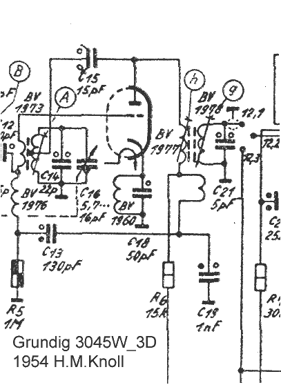
The principle used in the 5040W:
Simplified diagram:
.png)
(Translation of caption: Triode mixer stage with inductive feedback for IF damping)
Here is this part of the circuitry in the 5040W:
Full diagram:
.jpg)
On the IF transformer you see a small winding which is grounded on one side and connected to the mixer cathode of the ECC81. From the cathode there is a 50 pF capacitor to ground. The capacitor bypasses the RF current of the oscillator (98.2 - 110.7 MHz) to ground.
What is the purpose of that?
Triodes like the EC92 or the ECC81, when functioning as a normal amplifier (negative grid bias of 2 V and anode current of 10 mA), have an internal resistance of about 10 Kohm. When functioning as a mixer with negative grid bias and low impedance on the grid, it's around 28 Kohm. Because of the feeback from anode to grid due to interelectrode capacitance (Cg-a), this internal resistance falls to 8 Kohm if the grid is not "cold" at 10.7 MHz. To guarantee that the oscillator functions, however, a larger value for C94 cannot be used (blocking).
There is, however, the possibility to increase the internal resistance by using positive feedback. A coupling of the signal from the output to the cathode of the same stage. The formula for the tube is: Ri = [ 1 / S*D ]. If we examine the effect of the quantity D, which, for a given delta in the anode voltage Ua tells us what the corresponding delta in the grid voltage Ug1 would be, this means that a reduction in the AC voltage on the grid causes, through D, an opposite polarity voltage (feedback) from the output to the cathode, and the internal resistance Ri of the triode increases. In this way, the effect is increased -- the effect by which delta Ua causes a reduction of delta Ug1 - by applying a signal to the cathode with the correct phase. This effect can be pushed to the point that the stage oscillates. The way to see this is the following: The voltage between cathode and ground also appears between grid and cathode, if the grid is grounded. This is accomplished by C94 and the tap in the FM coil. It is exactly the same case as for normal -Ug1, you can also measure the voltage between cathode and ground, and the g1 signal appears across the cathode resistor to ground.
On Question 2:
The cathode circuit was seen by both as something to aid or initiate oscillation.
If it were negative current feedback (created by inductance), it could have this kind of function, but it is not likely that the oscillator won't oscillate at the resonant frequency of the inductive feedback coil.
Above its resonant frequency, a parallel resonant circuit behaves as a capacitance. Therefore it has no supporting function for aiding or initiating oscillation. That role is played by grid rectification, both to initiate oscillation, and to regulate or stabilize it.
Here is some supporting data.
Best regards, and have fun!
Hans M. Knoll
Attachments:
- Beschreibung der HF- Entdaempfung (69 kb) (Description of high frequency damping)
- Prinzip_ZF_Entdaempfung (44 kb) (Principle of IF damping)
- Original 5040W Mixer (28 kb)
To thank the Author because you find the post helpful or well done.
Final answers for Questions 1 and 2
(Translation of text originally by Hans M. Knoll)
Conclusion to Questions 1 and 2
In the course of further development of the 5040W 3D, this method with the coil for feedback to the cathode could no longer be used. The new circuit with the ECC85 was not developed just for the top-of-the-line models 5040 and 5050w 3D, but for the entire line for the year 1954. Therefore they would have had to put a second IF circuit in the box for the mid-range models. In addition, more attention had to be given to reduction of unwanted radiation in FS-Region III. Therefore the inductive coupling of the IF and oscillator couldn't really be continued. Every coupling coil with a small number of turns on each of the IF coils has an unwanted resonance, which could result in radiation of unwanted signals via the IF leads.
Here is a detail from the band filter version. You can see that the coupling coil is not a reasonable choice for damping:
For reasons that don't apply to the 5040W 3D because it has only one IF coil per box, the signal for increasing the internal resistance of the tube (as explained above) was fed from the anode circuit (cold side of the coil) of the mixer via a low pass coupling to the control grid.
To accomplish this, a current was derived from the opposite phase voltage at C10 (1 nF) was fed through the series circuit of C8 (115 pF) and the choke (2 uH) and coupled into C5 (50 pF). The resulting voltage on C5 was fed via the feedback coil (2 turns on the oscillator coil) directly to the grid of the mixer. In order that the RF from the previous stage could reach the grid unpurturbed, the 2 uH choke was used, which prevented C8 and C10 from shorting the signal to ground. The reduction of feedthrough (from anode to grid) was achieved as previously discussed. Throughout the production run it became apparent that due to manufacturing variations among various lots of the ECC85, the damping deviated too much from its target value.
Reason: The series circuit, which consisted of two capacitors and one inductor, always had problems, because of the reactance of the 2 uH choke and the 115 pF capacitor in the circuit (XL and Xc at 10.7 MHz are almost equally large and changing in opposite directions with respect to frequency). There was a lot of fluctuation in the current in the feedback coupling because of tolerances. The value of C8 was adjusted to 125 pF and later to 130 pF. You can see that by looking at later models.
What is now missing is the IF damping function.
As is often pointed out, if one wants to make further improvements on a circuit, the weak points have to be eliminated. A triode like the ECC85, functioning as a normal amplifier (grid bias = -2 V and anode current 10 mA), has a Ri of 6 Kohm. Functioning as a mixer with a negatively biased grid, it has about 28 Kohm. Because of the feedback from the anode to the grid, it gets reduced to 8 Kohm, if the grid is not "cold" at 10.7 MHz. (See the IF-bridge attachment, where this is explained.) It can be seen that an anode circuit with 30 Kohm impedance, but damped with 8 Kohm, only has an effective impedance of 6.3 kOhm and the amplification is therefore only 20% of what it would have been if a ECHxx or EFxx were used. Triodes have low impedance output.
Now comes the circuitry trick.
If you reduce the bad effect of the feedback via the anode-grid capacitance Cg-a, then Ri stays at 28 Kohm. It is even possible, and indeed common practice, that this 28 Kohm can be eliminated by the feedback coupling, which is indeed neutralization. The whole thing then works like a ECHxx or EFxx, which are indeed high impedance at their output.
The new circuit in 1958
With further development of the mid-range FM Box, for example, in the 2099W through 5066W, as well as in the new 6099W (actually first used in the 90U in 1955), the circuit technology for Ri damping was converted from low impedance to high impedance. You can recognize this by the following: The 1 nF capacitor is changed to 91 pF, then 95 pF, and finally 100 pF. The 115 pF capacitor now has only 15 pF. The choke the reduces the loss of HF stays at the same value. The resonance is now at 30 MHz, and the XL and Xc are far apart.
A description of this method as a bridge circuit (a bonus I'm giving you, since this hasn't been discussed yet), can be found here:
The new method for IF damping: .pdf
On Question 2:
C9 and the 60 nH choke function here as a resonant circuit. Having the anode current flow through it has a good effect. What does the anode current do? Herr Barkawitz's answer is very nearly correct. The true reason in this set, however, is different.
Here we're optimizing the discussion. The cathode circuit does that too. The RF stage, which was discussed in detail in Part 1, feeds the tuning circuit comprised of: C6, C11, and the inductor. From the centertap of the inductor, C5 is connected through the feedback coil to the grid of the mixer. To understand this better, here's a picture with the components we've been discussing, including the RF resonant circuit with output to the mixer stage.
.jpg)
The previous stage (the RF stage) can only have as much amplification as the quality of the circuit allows. Gain = S x Rz (transconductance of the tube x output resistor). This output resistance is however reduced by the input resistance of the mixer stage. In addition, the output is further divided between C5 and the input stage of the mixer. This can be reduced if C5 is increased. C5, however, is designed to work with R3. This time constant is critical. Otherwise there may be blocking (periodic interruptions of the oscillation).
Now what can we do?
Increase the input resistance. That is done with a resistor that has no siginificant effect at either DC or at the oscillator frequency. A resonant circuit which more or less covers the band 87.5 to 100 MHz. It functions as negative current feedback and as a method to increase the input resistance. Consider the case of a cathode follower, which does this by its very nature.
For a bonus, you find two exceprts from Technical books from Telefunken in Ulm. One about the influence of anode-grid capacitance on the internal resistance of the mixer tube, and as "7" the function of the negative current feedback on the cathode of the mixer.
Attachments:
- ZF_Bruecke (29 kb) (IF bridge)
- Stromgegenkopplung im Mixer (31 kb) (Negative current feedback in a mixer)
- Bandfilter_Version (22 kb)
To thank the Author because you find the post helpful or well done.
Pictures of the FM tuner
(Translation of text originally by Thomas Günzel)
Dear friends of the forum,
First a big "thank you" to Hans for the detailed and instructive explanations.
To provide a better understanding of how the FM tuner circuitry was built, I have taken some pictures and labeled some of the components.
The FM tuner is definitely the most difficult part, where a lot of "know how" and empirical knowledge was needed to get the design ready for production.
Therefore here are a few more questions for Doctor "Hans", who rubbed shoulders with engineers on both the development and production side:
1. How long did it take to replace the EC92 with the ECC85 for mass production?
2. Was the tuner built as a separate unit and separately tested?
3. How long did it really take in production to test a tuner?
4. Were the trimmer capacitors and adjustable coil cores sufficient for adjustment, or was it sometimes necessary to adjust the coils by bending (i.e., compressing or spreading) the windings?
Here are pictures of the tuner. For a larger view, simply click on the picture:
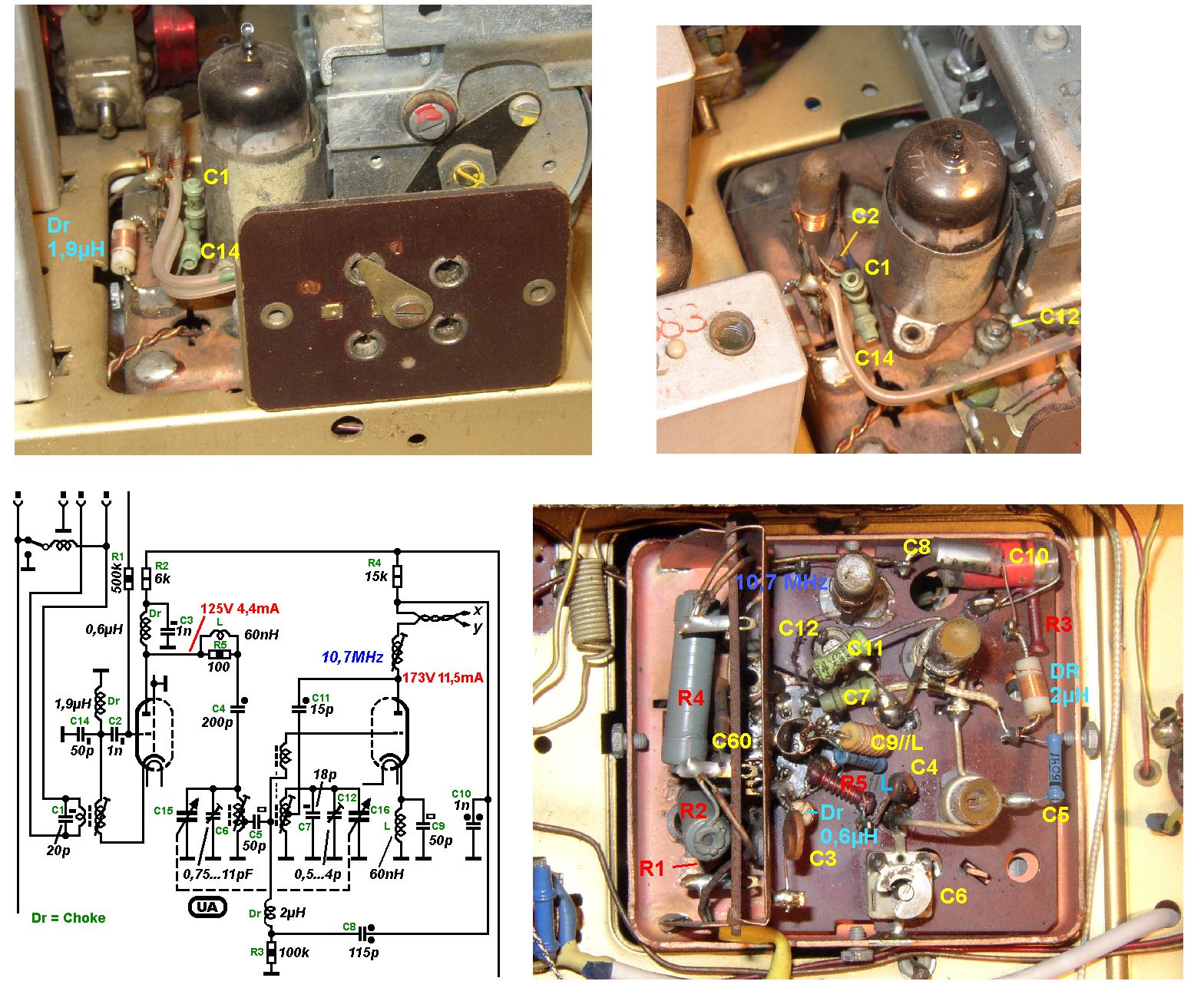
Enjoy!
Thomas G.
P.S.: Thanks to Werner Hauf, who provided his 5040W/3D for taking these pictures.
To thank the Author because you find the post helpful or well done.
Notes from mass production
(Translation of text originally by Hans M. Knoll)
Hello Thomas, hello forum friends,
Question 1:
It only took one season -- the EC92 was used in 1953 and the ECC85 was used in 1954. The 3045W from 1953 had the EC92; the 3045W/3D from 1954 already had the ECC85. In addition there were in 1954 the high end 5040W/3D and the 5050W/3D. The previous models in 1953 had EC92 and ECC81. And on the low end a whole bunch of table radios and consoles.
Question 2:
Yes - on 100% of all FM Boxes, bandfilters, and coils were tested with an apparatus identical to the radio and compared by brute force. Finding and repairing the problems in the finished radio (and there always were some) would have been much more complicated. At the final test, everything went a lot faster, since the components had been previously tested to be good.
Question 3:
About 2 minutes max with wobbler and oscilloscope including the IF check. With the EC92? 3 minutes? With the EC92 everything was more complicated and more likely to need repair, because of the neutralization of the oscillator to the antenna. Testing on account of the FTZ number: 100% of units were tested twice with less than 1 mV across the 300 ohm antenna terminals. With the ECC85 (with RF stage), this was only done in the final acceptance test.
Question 4:
Nothing could be adjusted by bending. The windings were stuck to the coil form with solvent. In addition, the FM coils were deep inside the FM box, locked behind 4 screws for a good seal.
Information:
The soldering was done with "Phantom Plugs" from Telefunken (we've talked about those here before); later with Grundig-made ones. That way the contact springs stayed centered, and damage to the tube pins due to the stiff wiring of the circuit was avoided. That was anticipated by the tube manufacturers. I'll show them here in case I don't find the previous thread where they were shown.
.jpg)
Here's a thread on this subject:
mir_unbekannte_telefunken_bauteile_spezial_roehren
HMK
To thank the Author because you find the post helpful or well done.
Discrepancies explained!
(Translation of text originally by Thomas Günzel)
Dear friends of the forum,
After some lengthly discussions behind the scenes, all questions regarding the FM tuner have been explained!
The corresponding posts have been updated!
Therefore, read everything above from top to bottom!
[A number of changes and corrections were made in the German thread, but none of it was translated until the final version - Tom A.]
A big "thank you" to Hans Knoll for his untiring effort and naturally also to Andreas Steinmetz for his valuable contributions to correcting the first comments.
Soon we'll continue, but let's give Thomas Albrecht a chance to follow up. [Thanks! This one was a lot of work!]
Thomas G.
To thank the Author because you find the post helpful or well done.
The Final
(Translation of text originally by Hans M. Knoll)
Hello Thomas, hello Herr Steinmetz,
Just about everything is correct. Some links and pictures still need to be tested for functionality.
To Thomas G.: No one has noticed that the voltges and currents on the ECC85 are swapped. The high current goes with the RF stage, etc.
Regards, Hans M. Knoll
Appendix: Hello Herr Barkawitz, I'm glad if this has helped you. Indeed you were not entirely uninvolved. As one can see, it was not so simple, to get it right on the first try.
To thank the Author because you find the post helpful or well done.
Thanks for the effort!
(Translation of text originally by Dieter Barkawitz)

Quote from Herr Günzel:
"After some boring discussions behind the scenes, all questions relating to the FM tuner have been explained!"
... and the reader has gotten smarter!
I read the contributions from Herr Steinmetz and especially from Herr Knoll with great interest and learned a lot about the vacuum tube technology from those times and the circuitry solutions that were used. It's great that we've still got access to such knowledge!
With great anticipation I await the next chapter in this very interesting series!
Regards, Dieter
To thank the Author because you find the post helpful or well done.
Continuations

To thank the Author because you find the post helpful or well done.
 Thread closed by a moderator. But replies can be made through a moderator.