hismasters: Repair & Restore of the HMV 1121
hismasters: Repair & Restore of the HMV 1121
This is one of the Mains sets I fancied even before collecting
It was packed accoring to my instructions including two layers of card with balls of paper between in front of the glass.


Appearance identical to the eBay photo
In the early 1970s as hobby I repaired old TVs and Radios. Later in 1978 I repaired current "AV" equipment as part of my job, getting it "fixed" was more important than originality!
But with Vinatge (this radio is about 62 years old at time of writing) or collecting there is the conflict between "use" (a Radio is meant to be listened to) and "Museum"/"Archaeological" approach to restoration or preservation. I'm not going to buy an old AM set and build in an FM head, or strip an old set and put in LCD screen and DAB radio. But for 1950s set I'm not going to use original resistors or capacitors. I regard a plug-in tube adaptor acceptable but changing base type or rewiring the socket for different type of valve unacceptable. What would I do with a 1920s set? Maybe leave it as a display piece if I can't repair using original parts? I have a 1934 Philips Superinductance and can't decide what to do about it!
See the cabinet "minimal" restoration on this article (link).
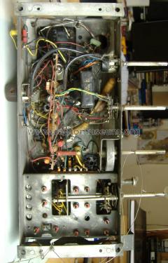
I first printed large copy of the schematic with the two pages combined to one and also the component layout on one page and took a photo of under the chassis (see Model Photos):
 Click for larger preview

Reduced size example of component layout
I indentified possible significantly faulty capacitors and looked for C24 the Anode DH77 to KT61 Grid (via S28 or C25 and R16) from the photo, schematic, usage, type and value. See "Replacing old Capacitors"
C24 is a metal can type and one end not easily accessible. C32 is a very large wax coated card cased Waxed Paper capacitor, so I disconnected the V4 anode end and put the capacitor leakage tester on it. It flashed slowly which indicated over 100M Ohm leakage at 300V. Not at problem at all!
So I powered up the set after I repaired the broken volume control. With the speaker off the baffle board it sounded terrrible but worked. Switching to any of the tone positions 1 to 4 there was a smell of burning and R20 started to glow! Ooops. Time to turn off!
I took out the KT61 output Beam Tetrode and plugged the DMM between grid and ground.(pin 5 is grid and 2 or 7 heaters). On powering up the DMM read 5 V. Bad. Should be near zero.

So obviously the "metal can" (often high quality ex-military paper capacitors in 1950) capacitor is useless.

It's got a rubber or plastic cover.
I replaced it with a 1uF 630V metalised polyester, which should be fine here.
Everything now happy? Well, unusually all the card & wax covered "wax" paper & foil capacitors seem fine. The set does use very many wax coated Silver Mica capacitors which rarely give trouble.
No, the SW2 band is totally dead. Even with local signal generator. Here is why (link) with repair.
Now everything is fine.
One bulb is gone, so I replaced all four with new 6.5V 300mA.
The loudspeaker cloth splits on re-assembley, so as I don't have similar dark coppery open mesh cloth to let the black baffle and speaker be a scale background I use a piece of coloured very sheer skirt.
Here is the set running on the bench with main lights off to make the scale illumination more visible
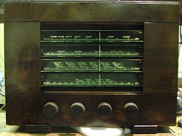
It works quite well on LW, MW, SW1 and SW2 with just about 1.5m of aerial wire (5'). There is no internal aerial, without some sort of aerial wire it receives nothing, which is normal.
The chassis actually has octal socket holes for the X78, W77 and DH77. There is an octal size hole too close to speaker at the front that the U10 wires come from. I suspect the chassis tooling is from the HMV 1120 which looks like same steel with Octal lineup of tubes.
I used the signal generator to check aligment (I only adjusted replacement C41 on SW2) and then to set tuning to a known position near the scale middle. I put a mark on the scale (there is a pointer) of the large drive cord wheel. This allowed near perfect "first attempt" clamping of dial cord to scale pointer on chassis refitting.
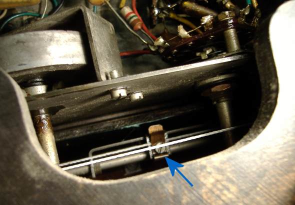
Drive cord to scale pointer clamp via underneath access hatch
Other Features
The Tone control is interesting. It has five positions:
- HiFi: Maximum treble and IFT 1 (L16 & L17) tuning swtiched to wider band, no treble reducing feedback
- High: Slight treble cut (C27 27pF feedback)
- Medium: Medium tone (C28 68pF feedback)
- Low: Maximum Treble cut (C29 200pF feedback)
- Bass Cut: dramatic bass cut by insterting 470pF C25 in series with KT61 grid with 330K grid bias load, also Maximum Treble cut.
The Radio/Gram switch is on the rear rather than on tone switch (Pye 39 JH, Pye 38 JH/E) or on waveband switch.

Final Result
(larger size uploaded to model)
To thank the Author because you find the post helpful or well done.