Homebrew radio -- Help
? Homebrew radio -- Help
Hi radio friends,
I have this homebrew radio, and i need help to identify the tubes ( all missing) and the correct power supply.
Is writing in chassis the name of the tubes, but i think that is not correct, because is 2 socket with 5 pins and 1 wtih top contact, and the tubes names is only triodo.
I did the schematic ( following the connections).
Please tell me where is the mistakes


Best regars
Carlos
Bild wurde zentriert.
To thank the Author because you find the post helpful or well done.
? Larger schematic and a few suggestions

Hello Carlos, I am glad you decided to restore this radio and post such good info.
It would be helpful if you could post an attachment with a larger version of the schematic, perhaps 4x larger. Gif format would give the cleanest results with a modest file size. A good way to prepare the schematic in gif format is to convert to grey scale, increase constrast or adjust "levels" to make the background white and the lines black, and then convert to gif using 16 levels. A higher number of levels in the gif file is OK if the background is solid white.
The larger schematic will help identify the function of the various stages.
One important thing to check is continuity on all the coils and transformers. It would also be good to know the resistance of each winding, as this will give some sense of the impedance ratio from primary to secondary. For example, the output Pilot audio transformer may be set up to drive a low impedance speaker or a high impedance speaker. If the secondary resistance measures less than 10_Ohms, then it will drive a low impedance speaker, but if you measure hundreds of Ohms, you will need a high impedance speaker, like a reed type, or you can use a modern low impedance speaker if you use a common tube type audio output external transformer between the Pilot transformer and the low impedance speaker.
If the Pilot audio transformers show an open, it may be possible to repair them. Sometimes the magnet wire corroodes right at the solder connecion inside the metal shield. This is easily corrected by resoldering. If the audio transformer windings are open, you still have a chance to repair them by inducing a high voltage at the terminals. I repaired the coil of a Baldwin reed speaker this way, and it has stayed functional over a year. I could explain the high voltage trick further, if needed.
As for the tubes, it may be possible to adapt more modern and inexpensive tubes to work with this radio. I have had some success with this type of substitution. I don't have the tube types with me, but I will look them up.
Perhaps our own Mr. Konrad Birkener, who has great experience with home brew sets, could advise further with tube identificaition and possible substituions.
The values for the power supplies can be chosen from the types of tubes that will be used. There is usually the filament supply, the negative bias voltage supply, the detector supply, and one or more B+ supply levels.
Generally, the filament supply will be less than 5V, the negative bias supply could range from -5V to -20V, the detector supply is usually around +25V, and the B+ supplies could range from 45V to 150V, with the higher voltages usually used at the output audio tubes.
These values would be good to start with, with the most important being the filament supply.
You could also check the various stages individually, with only the related tubes plugged in.
It would also be helfpul if you could share what kind of test equipment is available to you.
Good luck,
-Joe
To thank the Author because you find the post helpful or well done.
UX299 substitutes
Carlos, as promised, I am sharing some info about the inexpensive tube substituitions I have experimented with.
The tube I tried to emulate is the RCA UX299. This is a basic American filamentary triode from the 1920's with a 3.3V/60mA filament, 90V at the plate, -4.5V C grid bias in Amplifier mode, and 22.5V at the plate in detector mode. The maximum voltage gain is 6.6 and the transconductance is 425uS.
I tried three different types of more modern inexpensive tubes: The 3A5 7 pin minuature dual triode, the 5676 subminiature triode and the DM160 triode with a fluorescent green target at the plate.
The tube sequence shown here is:DM160, 5676, 3A5, UX299

The three substitutes were mounted in 4 pin sockets that matched the pins of the original UX199.
The DM160 and the 5676 also have voltage dropping resistors in series with their 1.3V filaments. I used light bulbs as resistors to drop from the 3.3V of the UX199 to the 1.3V of the two subminuature tubes.

If you decide on one of the subminiature tubes as your tube, you can just run all filaments at the low 1.3V voltage. It is also important to tie the voltage dropping resistor or light bulb to the positive side of the filament supply. If you use a resistor, the value is given by the voltage you want to drop divided by the filament current. And the power dissipation of the resistor is the product of these two quantities. Make sure that the power rating of the resistor is high enough so the resistor does not get too hot.
The easiest and least expensive of these three substitutes is the 3A5. The voltage is already 3V, which is good in the case of substituting for the UX299.
All three substitutes function in most of the sockets, but their performance will be different. For example the 3A5 has more gain than the original UX299. The internal tube capacitances are also different, and this will cause different performance in the RF or IF circuits. You may even get oscillations with the higher gain tube, that were not present in the lower gain tube. Sometimes, just lowering the filament supply is a good way to kill oscillations.
With the 3A5, you may also choose to use both triodes with the grids and plates tied in parallel, or ground the plate and grid of the unused half.
I have used these tubes in this old Silvertone/Trav-ler radio that I restored last year.

The three substitute tubes are visible on top of the radio. The sit in front of a 4.5V C cell. The bright rectangle to the left is a current meter in series with the detector tube 22.5 plate supply. It indicates about 300uA and serves as a tuning indicator. When I am tuned in, the current drops slightly.
This is the radio with the Baldwin speaker that was open, and was fixed with an externally applied high voltage zap.
With your chassis, you could start by trying the substitution on just the audio stage, to see how you like the tube operation.
Upon closer inspection, I see at the lower right of your schematic that you have an open Pilot transformer. You might be able to fix it with the suggestions I mentioned.
Regards,
-Joe
To thank the Author because you find the post helpful or well done.
? Schematic correct ?
Hi Joe, many thanks...obrigado
this picture is better.
I am not familiar with battery radios, and i need help to put the correct values of the power supply.
In the schematic the letter A= ?; the letter B= + 4V ? ; letter C= - 4 V ?; etc... ???
The Pilot transformer 399, is burned. I disassemble the transformer and he have one winding with 1100 turns, and two with 5400 turns.
the test equipment that i have: multitester, rf generator, tube tester ( not for condutance) and osciloscope.
regards
Carlos
Attachments:- Schematic (161 KB)
To thank the Author because you find the post helpful or well done.
? Transformers MF e Filter
Hi,
The two transformers MF have this values:
Winding +80 to P= 42 ohms
Winding G to F = 92 ohms and a 240pf condenser in parallel
The Filter :
Windings +40 to P and G to F = 45 ohms and a 800pf condenser in parallel.
The coils:
Coil nº 1= 10 ohms
Coil nº 2 = one winding with 2 ohms, and other winding with 1 ohm.
Coil nº 3 = 20 ohms
Regards
Carlos
To thank the Author because you find the post helpful or well done.
Schematic review
Hi Carlos, the new schematic is very clear. I reviewed it and have a few comments.
The wiring around tubes 3 and 4 does not seem correct. The two plates are tied together and to nothing else.
The various stage functions, as sorted by your tube numbers, seem to be as follows:
1.
Space charge tetrode mixer A441N. This tetrode is wired for space charge operation with G1 bypassed to ground and a high value 400k resistor going to power terminal G. According to the curves contributed by Wolfgang Holtman for the similar space charge tetrode RE074D, a couple of mA would be expected into space charge grid G1. So the 400k resistor means that weak space charge operation is being used. The purpose of space charge grid G1 is to increase filament emission by helping to accelerate electrons with a small positive voltage. Under this mode of operation, the plate voltage can be much lower than for a triode.
This ability to operate with a low plate voltage is what makes it possible for the plate to operate efficiently with just with the AC voltage being injected by the local oscillator at stage (2). On average, the plate sees 0VDC, and conducts with the positive peaks from the resonant LC circuit formed by the 1_Ohm inductor and the 500pF variable capacitor. The input RF signal is injected at G2, and mixes with plate current pulses to produce the IF frequency that is extraced by the IF transformer labeled filter. This frequency mixing method was known as Ultradyne and was invented by Robert Lacault
The RF signal is injected from the antenna circuit at G2. There is a missing coil in this circuit that would resonate with the 500pF RF tuning capacitor. You could make a transformer coil to plug in here, or you could plug a loop antenna into this coil socket. The missing RF transformer coil could be very similar to the local oscillator transformer coil because they operate with just a 55kHz IF difference. I could give further details on how to make the coil/transfomer. The inductance of the secondary of this coil, or of an external loop antenna, should be 168uH to resonate with the 500pF tuning capacitor at the 550kHz end of the AM band. 168uH=1/(4*500pF*(550kHz*pi)^2)
2.
Local oscillator A415 triode. The oscillator configuration is tapped inductor. The plate drives one end of the coil and the grid drives the other end. The common point to the two 1 Ohm windings is hard grounded. Normally, a local oscillator grid coil is AC coupled to the grid, with a high value resistor going from grid to the ground. If this were done here, there would be very little oscillator AC signal to drive the plate because the oscillations would self bias the grid negative. With the hard grounding of the grid, the grid will stay strongly biased and the oscillations will be strong enough to drive the plate. I would expect that the oscillations at the Mixer plate reach positive peaks between +10V and +30V. This value could be taken from similar Ultradyne designs. Perhaps Konrad Birkener could suggest a reasonable value for the oscillation peaks.
For proper winding orientation, the terminals of one of the windings should be reversed in the schematic, or you cold draw a dot on the upper left where the LO tuning capacitor is connected, and a dot on the lower left of the primary where the 0.01uF capacitor connects to the plate.
The plate has a choke or reactor load that serves to pass DC voltage while providing a high impedance at the oscillation frequency. The inductance of this plate load coil is probably 1mH or more. The power supply for the oscillator is brought in separately at terminal A. The voltage at this terminal could be determined experimentally to produce at least +10V positive peaks at the mixer plate. I suspect that you will not need to go much above 45V, but you could go a lot higher, perhaps to 100V, which also powers the screens of the output tubes from supply terminal A.
3. and 4.
The two IF stages with A-409 triodes. You shared in a private email that the IF is 55kHz. The Transformer you labelled "Filter" and the "MF" transformers should all be tuned to this frequency. It is possible that the turns ratio for the "Filter" transformer is different from the other two.
As I noted at the top, stages 3 and 4 do not seem wired correctly.
The volume control is implemented at this stage by varying the DC bias to the control grid of tube (3). Maximum signal gain is obtained when the voltage at the 750 Ohm potentiometer is zero volts. Increasing the grid voltage lowers grid impedance with forward bias conduction, and the grid signal is attenuated. Note that this gain control operation is the opposite found in AGC of later radios, where the grid bias voltage is made more negative to reduce signal gain.
Power terminal F supplies anode voltage to these plates. It is important that the anode votlage be sufficiently high to keep the grid from conducting with zero volt grid bias, which would attenuate the IF transformer signal. A voltage of 45V may be enough.
5.
Detector stage with A415 triode. The detection is done at the grid but this is not a grid-leak detector because the grid is forced to 0VDC potential by the grounded secondary of the last "MF" transformer. When detection is done at the grid, it is important to keep the plate voltage low, so that the electron flow that occurs with detection at the grid is not diverted to the plate. This is the opposite plate voltage requirement from the two IF stages. Note that the 1Meg resistor at the detector plate makes it possible for the detector stage to share the same power supply as the two IF stages, while keeping it's plate voltage low.
The 200pF at the plate and the inductor with 20 Ohms of internal resistance should form a low pass filter to extract the audio, but an additional capacitor, perhaps 100pF, would be expected at the output of the 20 Ohm coil. The 200pF cap also serves to isolate the 20pF coil from the plate at the IF frequency and prevent oscillations in the detector tube.
The 0.005uF cap couples audio to the audio preamp stage.
It would be interesting to hear more from other RM members about the merits and operational details of DC-grounded grid detection. Perhaps Wolfgang Holtman could help here. He has done extensive work on detection.
6.
Audio preamp B406 triode. Takes audio input at the grid with a 100k resistor. This resistor is probably present to avoid oscillations that would be caused by plate-to-grid internal (Miller feedback) capacitance as it is loaded by the primary of the audio driver transformer.
This is your open transformer. it sounds like you are attempting a rewind. That is good! Just use fine wire of a similar guage. The exact number of turns is not important, except that the two halfs of the secondary should have the same number of turns. But even this is not critical, as long as the ouput triodes are run in class A operation. If the number of secondary turns is matched to 10%, that is good enough. If you find that you can't fit all the turns, you could cut back the total secondary turns back, to maybe just 3000. I have not rewound audio transformers.
Perhaps another member can advise about winding the two secondary halfs with a pair of magnet wires. This is called bifilar winding, and guarantees perfect match in the number of turns, and saves winding labor. The down side of bifilar winding in this case is a substantial increase in secondary output capacitance. This capacitance could be hundreds of pF between the two windings.
When wiring the secondary be sure to have opposing voltage phase at the ends.
7. 8.
Power output stage B443 power pentodes. The B443 is the first power pentode ever produced. It was invented by Telegen at Philips. There is no separate pin for G3, the suppressor grid, because it is connected to the center point of the filamentary cathode.
The published curves show that the anode voltage can be between 100V and 150V. One tube could deliver 1Watt of audio power, and well over 2W in the push-pull circuit you have. You could use a modern 3V power pentode that was intended for portable radios after 1939, like the 3S4 or 3Q4, and just lower the plate voltage to the recommended values (90V for the 3Q4).
The plate curves for the B443 at http://www.mif.pg.gda.pl/homepages/frank/short/064/b/B443.gif
suggest a grid bias of -19V when the plate and screen voltages are 150V. You can reduce the G2 Screen voltage and the GI control grid voltage values in the same proportion for lower supply voltages. If G2=+100V, then G1 should be -9V. The control grid bias is supplied at power terminal E.
Note that the screen voltage is supplied by power terminal A, which also supplies the anode of the local oscillator. Perhaps this means that the required voltage here is higher than the minimum 45V I thought necessary for the local oscillator.
The screen voltage will set the standing current of the tube. This current is approximatelly proportional to the square of the voltage. So cutting G2 from 150V to 100V, will reduce the current in about half, from 18mA to 8mA.
The single ended load impedance with just one tube should be 20kOhm, according to the plate curves. In push pull, the load impedance should be half that at 10kOhm. You could drive a reed speaker by connecting it directly to the two plates, or you could use an impedance matching transformer to drive a low impedance 8 Ohm speaker.
Power terminal D supplies the plates, and can be the same as the screen voltage. The only reason to have a higher plate voltage is to increase the maximum possible power you can drive. Increasing the plage voltage has little effect on stage gain.
This has been an interesting radio for me to learn more about SuperHet technique in the 1920's. This set is a homebrew set, so it is only natural that you should experiment and learn from it too.
Regards,
-Joe
To thank the Author because you find the post helpful or well done.
? Schematic correct ?
Hi Joe, many thanks
You are correct, the wiring around the tubes 3 and 4 may not be correct.
I think that i found the problem...someone has changed the position of the valves and the transformers MF.
In the picture of the chassis in the right corner, you see the Filter, and the two Tranformers MF, and someone changed the position of the MF( the left side of the filter).
I think the tube is midle of the filter and the 2º MF.
I will redesign the scheme, because it changes everything.
Best Regards, and thanks
Carlos
To thank the Author because you find the post helpful or well done.
Inspiration from 1930s
Hi Carlos,
to correct your schematic, use the inspiration from constructures of superheterodyns in early 30s.
Viktor
Attachments:
To thank the Author because you find the post helpful or well done.
others schematics
Hi Victor,
many thanks for the old schematics.
I think that my homebrew radio works in the past, and now i wanted give it back to life.
this is the wire conections.
I put the nº of the tubes, and the name that i found writing in the chassis.
The diferences between the wiring in the 1º post, and this wiring, is the position of the first transformer and the tube nº 4.
I think that is the correct position.
Carlos
Attachments:- wire conetions (170 KB)
To thank the Author because you find the post helpful or well done.
? Correct tubes line up?
Hi
This is the "new" schematic, with the position changed between the sokets of the tube nº 4 and the first transformer MF.
the radio work with this schematic?
In the first post, i put the possibility of the tube nº 1 be the A441n, but this tube have the anode contact on the side, and my radio have one terminal on the top.
Because that i think that the first tube are the A442.
This is correct ?
Regards
Carlos
Attachments:- Schematic (161 KB)
To thank the Author because you find the post helpful or well done.
Schematic looks good
Carlos, the schematic seems correct now. The IF stages for (3) and (4) are wired conventionally. The new wiring for the front end mixer tetrode also changes it's operation. I think you wanted to mark tube (1) with A442 which is a screen grid Tetrode, and not A409, which is a triode.
A few changes to my earlier assessment are in order:
1.
Ultradyne Mixing tetrode stage A442. The two grid connections G1 and G2 are reversed from the original drawing. This means that now G2 is the grid with the bypassed DC positive bias, and G1 is the sensitive input grid for the RF signal.
The AC bypass capacitor also serves to shield the large local oscillator voltage swing that is present at the plate, so that very little Local oscillator signal is radiated back out to the antenna circuit by capacitive coupling. The shielding action of G2 reduces the capacitance from Anode to G1 to a specified value of 0.01pF. In a triode, or space charge tetrode, which was the previous configuration, this capacitance is a few pF.
Under normal amplifier conditions, with a DC voltage at the plate of 100-150V, the maximum obtainable DC gain from G1 to the Anode is a specified 280x.
But this stage is operating in Ultradyne mixer configuration, with 0 volts DC and a few tens of local oscillator AC volts at the plate.
Screen tetrode voltage/current curves at the plate have a complex kink as shown in this graph that I borrowed from this thread by Prof Ing Dietmar Rudolph about beam tetrodes:

The Ultradyne operation with relatively low plate voltage means that the negative resistance part of the curve, shown below 60V sloping downward in this example graph, will be in use here. The applied AC from the local oscillator to the plate will sweep the entire kink region below 60V. The net result of this sweep could be a relatively high average plate impedance and a relativelly high conversion gain from the input RF to the IF.
Ultimatelly, the operating behaviour of this stage will be set by the voltage that develops at the screen grid G2. The 400k resistor driving this grid suggests that low screen grid voltage will be used. The data sheet calls for 100v at G2 in normal amplifier configuration. But a reduced voltage at G2 reduces the average plate current and the average loading on the local oscillator.
It will be interesting to see how well this mixer works.
3. 4.
Two IF stages with A409 triodes. These two stages are wired identically, and are both under forward grid bias volume control. A higher forward bias attenuates the grid signal by grid loading. Having two grids under this control is better than just one because the required loading on each stage is much less to obtain the same volume attenuation. When very strong stations are received, it may not be possible to completely attenuate the volume to zero, as is usually done with volume potentiometers in the audio stages of more modern receivers.
The resistance values you gave for the "filter" IF transformer suggest that the turns ratio is one. The relativelly high value of 800pF capacitance, suggest that this is a relatively low impedance transformer.
The other two "MF" transformers seem to have a turns ratio of 2x, and a higher (4x) output impedance. The capacitance on the primary should be different than the capacitance of the secondary, by about a factor of 4. Perhaps the primary has a 800pF cap and the secondary a 240pF cap?
Usually, a triode IF or RF amplifier includes a method to neutralize internal capacitance from plate to grid because this capacitance reacts with the inductor load, and tends to cause oscillations with interaction with the input grid circuit. In this case, the relativelly high capacitances in parallel with the input transformers (240pF) make the small internal grid-plate feedback (Miller) capacitance insignificant. The modest 1mS transconductance of the A409 triodes is another factor why oscillations are not expected.
If a much higher IF frequency, such as 455kHz, had been chosen, a way to prevent, or neutralize, oscillations in the triodes would have been necessary, because smaller resonating capacitances would have been used.
The grid bias attenuator method of volume control can also be used to kill oscillations in the IF stages, should they arise.
----------------------------
Carlos, you have been providing very good info, and this has been a great chance for me to study a European design from the late 1920's.
Regards,
-Joe
To thank the Author because you find the post helpful or well done.
image size

A non-technical remark: please try to post inline images in the right (maximum) size, otherwise the page display will go out of bounds. If you need larger images, use the "attachment" function in the editor.
Good luck with your efforts!
Regards
Mark
To thank the Author because you find the post helpful or well done.
Schematic corrections
Hi Mark, sorry for the "big" image.
I correct the image, and use the "attachment" function.
Hi Joe, i make a mistake when i drawing the schematic. The transformers MF, have only one capacitor in the windingin F to G and is 240pf.
Regards
Carlos
Attachments:
- schematic (161 KB)
To thank the Author because you find the post helpful or well done.
Gains and Bandwidth
Hi Carlos, I think your schematic is correct now. The capacitance and coil resistance values you gave can be used to start estimating the voltage gain and bandwidth for the IF amplifier.
The 800pF caps of the "Filter" IF transformer need 10mH to resonate at 55kHz. The 45_Ohm resistance limits the Q to 80 at 55kHz. The highest possible Q of each side of the transformer, can be found as the ratio between the identical reactances of the cap or inductor at resonance, and the series resistance. The magnitude of the reactance of L or C at 55kHz resonance is 3.6kOhms. So the maximum realizable Q is 3.6kOhms/45Ohms=80.
Q, or Quality factor, is also a measure of bandwidht for the tuned circuit, In this case the smallest possible bandwidth is 55kHz/80=700Hz.
I have been saying highest possible Q and lowest possible bandwidth, because external loading by the plate resistance of the tubes will reduce the Q and increase bandwidth.
If this tuned circuit had no series resistance, but had some parallel resistance, the parallel resistance would have to be 80*3.6kOhms, or 290KOhms to get the same Q.
This equivlance establishes a relation to the effect of internal plate resistance on the tuned LC plate loads. The plate resistance of the front end mixer will be the least predictable because it will be an average resistance as the AC from the LO turns the mixer plate on with positive voltage peaks. And the tetrode plate kink complicates things further. I see that the new value for the resistance bias to the screen is 100kOhms. This will reduce the overall operating impedance of the tube by running the tube at higher current.
I would not rule out the possibility of the plate impedance being hundreds of kOhms. This will be best figured out by measurement. We could talk about how to measure mixer transconductance ( grid voltage to plate current gain), and plate impedance when you start to power up the set.
The A409 triode IF stages are easier to figure out because they operate with steady DC voltage and current bias.
The A409 has a specified plate resistance around 10kOhms, and a transconductance of 1mS. The maximum realizable voltage gain is the ratio of these two numbers, or 10. The 10kOhm value of plate resistance is valid for zero grid bias, which is the case when the volume control is set for maximum IF gain at 0V DC.
The 10kOhm plate resistance limits the Q at the primaries of the "MF" transformers to 3, but if the primary is loosely coupled to the secondary, the Q could be higher, perhaps twice as much. The reactance seen at the primaries of the "MF" transformers should be similar to the "Filter" transformer, judging by the similar DC resistance, and proportional capacitance.
The 2x ratio in resistance between windings of the "MF" transformers suggests a 2x turns ratio. A 2x turns ratio means 2x voltage and 1/2x the current, which is to say 4 times the impedance. So the resonating capacitance for the secondary should be 800pF/4. The actual value you show is 240pF and this is in reasonable agreement.
Under these conditions of impedance and Q, the voltage gain for each IF stage should be around 20. A factor of 10 comes from the tube, and a factor of 2 from the "MF" transformers. This adds up to a total IF gain of 400x. This compares favorably with the gain of most IF amplifiers in tube radios all the way to the end of the tube era.
The bandwidth of each IF stage should be around 10kHz, and half that for the combined two IF stages.
With this much gain, I am pretty sure you wil run the volume control well below maximum.
Another interesting effect of the volume control in this radio is that it increases IF stage bandwidth by the same amount that it lowers the gain. So strong stations will have more treble because the volume will be run lower. A big antenna will also increase treble because you can lower the volume.
Another interesting lesson I learned from the low 55kHz IF frequency is that relatively large capacitors are present at the grids of each stage. 800pF for the first, and 240pF for the second. The internal capacitance between the plate and grid of the A409 is specified at 4pF. This is also called the Miller feedback capacitance, and is known to cause oscillations if it is too large, when compared with the total capacitance from the grid to ground. In this case, the ratio between 4pF and the two capacitors drving the grid is 1/200 and 1/60. This ratio can be considered as an attenuatioin from plate to the grid circuit. There should be no danger of oscillation because the tube voltage gain is no more than 10. (A more complete and rigorous explanation was put forth by Frederick E Terman in his popular series of books about radio engineering starting in the 1930's. Look under the topic of input grid admitance. You can also find an exploration of oscillations in RF triode amplifers at the end of this thread.)
I just realized that I did not address the floating 2MegOhm resistor at the grid of the audio driver stage. This resistor should be driven with a negative bias voltage. A good value to use might be half of the plate voltage divided by the voltage gain (mu) of the B406, which is 6. For example, with 100V at the plate, the grid should be biased with -8V. If this bias level draws too much current through the driver transformer to the point of causing transformer saturation and distortion, the bias voltage could be made more negative, but at the expense of lower maximum voltage swing at the grid.
Good luck with the restoration. Keep us posted with your progress.
-Joe
To thank the Author because you find the post helpful or well done.
? what modern tubes, for the replacement ?
Hi Joe,
many thanks for your explanation of the operation of the circuits this radio.
I will take some time to restore this radio because I also have other projects to finish the restoration.
The next step, is found modern and inexpensive tubes for replace the original, and for that i need your help.
For the A-409 a have this information :
www.carnets-tsf.fr/tubes-electroniques/remplacement-valve-a409.html
For the others tubes i don't have.
Best regards
Carlos
To thank the Author because you find the post helpful or well done.
Using substitute tubes
Hi Carlos,
This is the first time that I am looking at 1920's European tube characteristics. Perhaps other members could share their experience with substitutions.
Let's make a list of the tube types that you need with a few key parameters, and possible substititutes:
A442 (1) Tetrode mixer
Transconductance or gm=0.7mS=0.7mA/V
Voltage gain or mu=150
Screen voltage=75
Anode draws 2mA at 100V, G1=0V, G2=75V
This is a difficult one to find a substitute. Tetrodes became rare types after the 1920's, so the challenge is to find a pentode where G3 is brought out separatelly, so it can be wired to the plate for tetrode operation. A possible choice might be the 1LN5 Loctal pentode operated as a tetrode, with G3 tied to the plate. Remember that this tube only needs 1.4V at 50mA at the filament, so you will need a total of 32_Ohms in series with the filament. You could experiment with placing the resistor on the positive side or the negative side of the filament. I remain very curious to see a plate curve family for the A442, or the 1LN5 in tetrode operation.
A415 (2) (5) Local Oscillator Triode and Detector Triode
Transconductance or gm=2mS=2mA/V
Voltage gain or mu=15
Anode draws 4mA at 100V with G1=0V
One half of the 3A5 tube seems like a very good fit here. If you use a 3V filament voltage it is important to use the triode that has the grounded end of the filament for proper detection. In the oscillator position, you could experiment with parallelling both triodes together to get a stronger oscillation, or try one triode or the other. Note that with 3V filament operation, one triode will have 1.5V more cathode bias than the other.
A409 (3) (4) IF Triode
Transconductance or gm=1.2mS=1.2mA/V
Voltage gain or mu=9
Anode draws 8mA at 100V with G1=0V
This triode runs at a higher current than the A415. Perhaps both halves of a 3A5 could be used in parallel to get proper operation of the volume control with 3V across the filament. The anode current would be about right, but total transconductance would be much higher at 3.6mA/V. One easy way to cut back the transconductance would be to cut back on filament voltage.
B406 (6) Audio Driver Triode
Transconductance or gm=1.4mS=1.4mA/V
Voltage gain or mu=6
Anode draws 18mA at 100V with G1=0V
The higher current of this triode suggests a 3Q4 pentode, operating in triode connection, with it's screen grid G2 tied to the plate. The mu of the 3Q4 in triode connection is about 10.
B443 (7) (8) Audio power output pentode
Transconductance or gm=1.8mS=1.8mA/V
Voltage gain or mu=100
Screen voltage=100V
Anode draws 18mA at 100V, G1=0V, G2=100V
The 3Q4 Pentode would work here, but with the plate voltage running no higher than 100V.
Note that there is a lot of similarity in the DC performance of these tubes. A number of more modern tubes will work in this radio.
The triodes are all of the medium to low mu type, and their transconductance is around 1mS. The larger difference is how much plate current they draw.
The low frequency operation of the IF stages made it easy to select a the 3A5 triode without paying much attention to internal capacitances.
Summarising, you may be able to get this radio to work with one 1LN5, four 3A5, and three 3Q4 substitutes. All of these tubes, or their European equivalents, are inexpensive and easy to find.
Good luck with the search, we could all learn a lot from the results you obtain with the substitutes. And alternative solutions may be used, if dificulties arise.
Regards,
-Joe
To thank the Author because you find the post helpful or well done.
Philips tubes plate characteristics
Hi,
characteristics of batery Philips tubes are here, for some tubes. But A442 is missing.
Viktor
To thank the Author because you find the post helpful or well done.
? More on tubes
Viktor, thanks for the reference to the tube curves.
The only tetrodes that are referenced are shown in Space Charge configuration, with g' as the first grid tied to 12V or 18V, and the second grid g as the control grid. The Transconductance "S" and voltage gain "g" of space charge tetrodes is similar to that of triodes, but at at one tenth the plate voltage.
I looked a bit further for possible tube substitutes, and a couple more came up for consideration to replace the A442. One is the 1LC5, which is similar to the 1LN5, but operates with a lower screen voltage of only 45V. Another is the 1LG5, which is the remote cutoff charteristic version of the 1LN5. This should be fine, because the grid is operated at 0V, anyway.
Another class of tubes to consider for Screened tetrode service is the pentagrid converter tubes, with the appropriate electrodes shorted together.
I own a sample of the 1LC5 pentode. When I get back from vacation in two weeks I plan to trace it's curves in tetrode configuration.
I wonder if someone has an A442 that they could curve trace and show the plate curves.
Interesting to note that in the triode era, the common set of curves on data sheets was a family of grid voltage to plate current curves. After more electrodes were added, the plate characteristics became more important to show because they showed more unique features.
Regards,
-Joe
To thank the Author because you find the post helpful or well done.
? Tubes substitutes?
Joe, many thanks.
Now go i buy the tubes substitutes, and make a power supply and repair the transformer.
Search the WEB, i found the tubes characteristics in this page
tubedata.itchurch.org/sheetsA.html and have the curves of the A442.
If a have more questions (and i think that i have), i tell you.
To thank the Author because you find the post helpful or well done.
Question?

Dear Carlos,
please dont call Your final thread a question.
The answers are given and You expressed satisfaction. Thats it. Would You agree?
Best regards,
KoBi
To thank the Author because you find the post helpful or well done.
information
Hello Konrad,
I agree with you.
Sorry.
Regards
Carlos
To thank the Author because you find the post helpful or well done.
Tetrode plate kink
Hello Carlos,
The material posted so far is enough to get you going on your restoration effort. But my suggestions are just that: suggestions. Only the actual application of the tubes can reveal the actual results. This is particularly true with the A442 tetrode mixer.
I have been focused on the plate voltage/current sweep characteristics with fixed G1 and G2 voltages because the large local oscillator sine wave will sweep the plate voltage right through the tetrode kink in the plate characteristic.
The curve sweeps shown in the data sheets at the link you posted, are for G1 voltage sweep and a plate current output with fixed G2 and fixed plate voltages. These curves relate directly to the normal use of a tetrode as a small signal RF amplifier. These grid voltage/plate current sweeps at high fixed plate voltage don't cover the kink in the range of voltages that the plate will get from the local oscillator.
Additional information about the application of Philips tubes in 1932 has just been posted by Thomas Lebeth - thank you Thomas.
The thread includes two pdf files, the second of which includes material about tetrode mixers, but with screen grid injection of the local oscillator sinewave, instead of the plate injection that your circuit has.
The text of the pdf files is in German. OCR could be done with Google's Softi to obtain the german text, and then a Google translation from German could be done. I have not read this text, but have used this process occasionally.
---------------------------------------------------------
A note about the tetrode plate current kink shown in the graph above:
When electrons hit a plate, there is always some secondary emission. If the plate voltage is high enough, these secondary electrons are attracted back to the plate and there is no net effect on plate current. If the plate voltage drops much below the screen voltage, some of the secondary emission electrons don't reach the plate, and end up at the screen, thus increasing screen current, while reducing plate current. A further reduction of plate voltage will eventually slow down electrons approaching it sufficiently, that secondary electron emission is reduced, and plate current increases with reduced plate voltage. Ultimatelly, when plate voltage approaches 0V, the plate voltage drops again.
This N--- shape I just described in the plate current of the screen tetrode contains positive resistance for the rising current slopes and negative resistance for the falling current slopes. This means that the net average impedance seen at the plate by the IF load circuit and the LO coil could be fairly high, as the positive and negative resistances cancell out (the more mathematically correct word here is conductances, which is the inverse of resistances) to leave a high resistance (low conductance) at the plate.
The physical shape of the plate has an effect on the net secondary emission, so it will be interesting to see what kind of tetrode behaviour will be seen when I sweep the plate of my 1CL5 with the supressor tied to it. I will have to try different grid combinations that emulate a screened tetrode, such as:
1.Tie G1 to a low possitive voltage to obtain space charge operation, use G2 as the control grid, use G3 as the screen and the plate will be the plate.
2.Tie G2 and G3 together as the screen grid for the 1CL5 in screen tetrode mode.
I suspect that these two configurations will have a more pronounced kink because the plate electrode is made up of just the smooth plate. When G3 is tied to the plate, it should retard secondary emission loss somewhat, when compared with just the plate.
Now I really have to make these plate sweeps to find out. I will report back here when I get back from vacation.
Regards / Cumprimentos / MFG.
-Joe
To thank the Author because you find the post helpful or well done.
Contemporary American RF Tetrodes
The following graphs show curve families for American RF tetrodes from 1935 that are nearly contemporary with the A442 Tetrode from 1927. These curves serve to illustrate RF Tetrode behaviour in the kink region with low plate voltage. Types 24A and 36 have a sharp cut-off characteristic, and type 35 has a remote cut-off.
The first horizontal division at the lower left of each graph is the region of interest for the mixer behaviour in this homebrew radio.
The width of the kink region is a function of screen voltage. Increasing the Screen bias voltage has the affect of widening the kink region. The shape of the kink also changes as a function of Screen voltage.
Unlike the A442, which has filamentary cathode, these American tubes have a unipotential indirectly heated cathode.


Regards,
-Joe
June 24th 2009
The american tube type 32 is a closer match to the A442 Tetrode because it is also a filamentary cathode tube. The filament of the 32 runs with 2V at 60mA, while the A442 filament runs with 4V at 60mA. The follwoing plot shows the plate characteristic for the type 32.

These curves also reveal that the control grid characteristic has a sharp cut-off. Transconductance is 650uS and the amplification factor is around 700.
Regards,
-Joe
To thank the Author because you find the post helpful or well done.
1CL5 curves
As promised, I have curve-traced the 1LC5 and 3A5, upon return from my vacation. The curve traces were photographed on a Tektronix 575 curve tracer.
First, the 1LC5 in pentode connection:
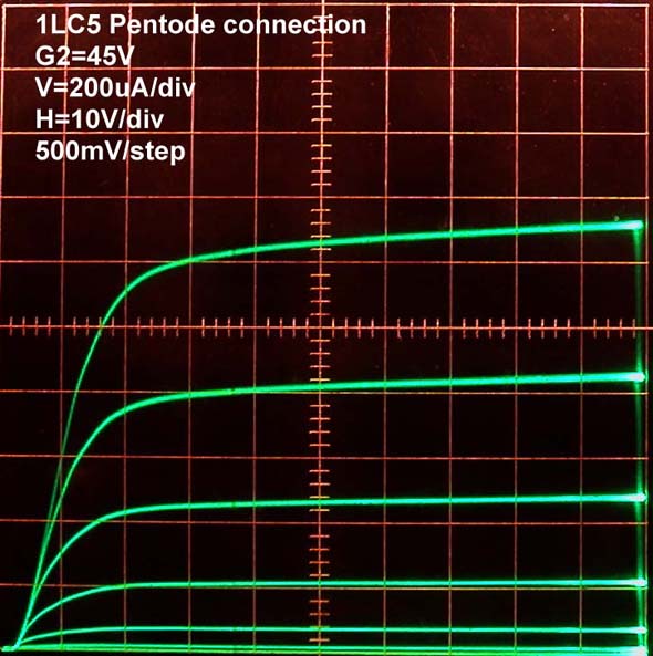
Now in one of two possible tetrode connections, the suppressor grid G3 tied to the screen grid G2:

and in the other tetrode connection, with suppressor grid G3 tied to the plate:

Both of the tetrode-connected curves show the classic tetrode kink, but there is not dip in the cuves around 20-30V because a relatively small portion of the plate secondary emission is being captured by the Screen grid connection.
The portion of the tetrode plate curve that would show the current dip will not be important in this mixer if the Local oscillator ampitude stays below +20V.
So the first two horizontal divisions of these plots, up to 20V, are the important region for the mixer.
The first of the two tetrode-connected plots (G3 tied to G2) shows that the plate is conducting fully and entering the horizontal high impedance regime under 10V.
The second tetrode-connected plot (G3 tied to plate) shows a steeper lower impedance characteristic around 10V.
Higher impedance at the plate gives higher gain at the IF frequency, so the preferred tetrode connection is with the G3 tied to G2.
Two factors contribute to the relatively mild tetrode kink: One is the presence of the unwanted suppressor grid, which disrupts collection of the secondary emission by the screen grid when the suppressor is tied to the plate, and the other factor is the unusually large diameter of the 1LC5 plate. If the plate is further from the screen grid, more of the secondary emission is re-captured by the plate, thus preventing the reduction in plate current at the kink.
For completeness sake, the following 2 plots show triode-connected cuves for the 1LC5. The first plot is in the same scale as the previous tetrode- and pentode-connected plots.


Regards,
-Joe
To thank the Author because you find the post helpful or well done.
3A5 curves
The important part of the 3A5 triode behaviour that I measured, is the grid conduction, because this is usually not specified in data sheets. Several stages in this radio bring the grid into forward bias, including the Local Oscillator, the IF stages, when the volume control is turned down, and the detector.
First, the classic plate cuves:

Now the grid current sweeps, taken at two different scales.

This plot covers 5V of forward bias on the grid, under a squence of plate voltage steps, up to 20V. Two important features can be seen here. One is the slope of the curves, which gives the conductance of the grid, or the inverse, which is the impedance. The other is the strong effect that plate voltage has on grid resistance.
When the grid is biased at +2.5V, the grid impedance is 1kOhms and the current is 1.4mA when the plate voltage is zero. But when the plate voltage is raised to 20V, the grid current drops to 400uA, and the impedance increases to 2.5kOhms. This effect is very important for local oscillator operation. A high plate voltage allows for a relatively large positive swing at the grid.
-----------------
The following plot magnifies current conduction near 0V bias. This is most useful to determine grid loading on the IF transformers.
The detector in this radio has the grid DC biased to ground through the IF transformer coil. So the important conduction behaviour is at the central vertical axis. Note how the grid conductance is strongly affected by the plate voltage. There is easily a 5:1 variation in the slope (conductance) of the grid at zero volts, as the plate voltage increases up to 20V.
At audio frequencies, the grid is grounded trough the IF transformer, so there is no detected audio voltage avaialbe at the grid. This is not a grid-leak detector because there is no grid-leak resistor and capacitor combination for audio voltage to develop.
So the audio signal appears only at the plate. It is necessary that the transfer function from grid to plate be non-linear for audio detectoin to occur. The triode plate curves above show that the plate will conduct 200uA at 20V when the grid voltage is zero volts, but the plate current drops to zero when the grid drops below -5V.
This is anode bend detection. It is necessary for the plate voltage to be low, such that the plate current can be turned off on negative peaks. The amplificaiton factor mu=15 for the 3A5 means that the conduction caused by 15V at the plate can be cancelled by -1V at the grid.
In other Anode-Bend detectors, a higher plate voltage is accomodated by supplying a negative grid bias to keep the triode on the edge of conduction. These two voltages are usually ratioed by the amplification factor of the tube.

Regards,
-Joe
To thank the Author because you find the post helpful or well done.
DC90 and DF97 as substitutes
Two possible European battery tubes for use as substitutes, are the DC90 triode and the DF97/1AN5 pentode in tetrode connection.
Regards,
-Joe
To thank the Author because you find the post helpful or well done.
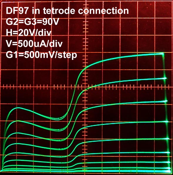
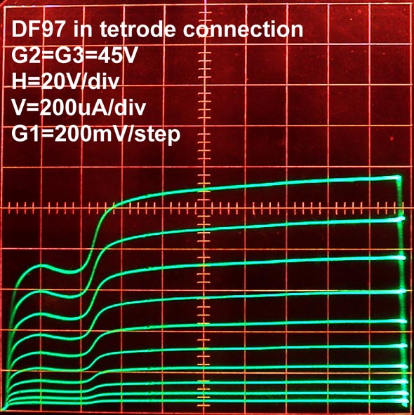
DF97 - Curves in Tetrode connection
The following plots show the DF97 pentode wired as a tetrode in two different configurations.
The tetrode kink always starts when the plate drops below the screen voltage.
The smaller diameter of the DF97 plate allows for more secondary emission electrons to be collected by the screen grid, in particular when the tetrode connection has G2 and G3 wired together, as the tetrode screen. This produces the very sharp tetrode kink when the plate voltage drops below the 90V at the screen.
Reducing screen voltage to 45V reduces plate current, and softens the tetrode kink because electrons hit the plate with less velocity thus producing a smaller proportion of secondary emission.
When G3 is tied to the plate, many more secondary emission electrons from the plate, are collected by G3, producing a much softer tetrode kink when the plate voltage drops below the screen. In this set of curves with 90V at the screen, the secondary emission current appears to perfectly cancel current increase that a higher plate voltage cause. The horizontal section between 20V and 60V is a region of extremelly high impedance, making it possible to achive very high Q and gain in a resonant LC load.
The flat region of the tetroke kink has the highest voltage gain of the entire curve. The plate impedance with 150V at the plate, 90V at the screen and 0V at the control grid, is around 300kOhms. The impedance of the plate on the same curve at 50V is easily 10 times higher. The 1mS transconductance seen between the two adjacent curves with G1=0V and G2=-0.5V combines with the very high plate impedance for a plate voltage gain in excess of 3000. The plate impedance between 20V and 60V can be fairly approximated with a current source.

In this configuration, with G3 tied to the plate, a reduction of screen voltage drops the current and moves to the kink to the left, as expected, but without a significant change in the tetrode kink.

The conclusion to be drawn is that the DF97 simulates a 1930 tetrode quite well, in fact, better than the 1CL5 shown above. This is most relevant for circuits with the plate voltage operating below the screen voltage. In the particular case of the Ultradyne mixer in this radio, the DF97 or the 1CL5 shown above should work very similarly if the plate swing stays below 20V. The most important characteristic of the curves for the Ultradyne mixer is the strong conduction of the plate at very low plate voltages.
Regards,
-Joe
To thank the Author because you find the post helpful or well done.
power supply
Hello Joe,
Sorry for the delay, but i don't have any progress in the radio.
Your explanation about this valves is expectacular, and will be very useful, not only for me but for many people.
Many Thanks.
In this moment i have the tubes and i work in the power supply.
in this link, you can see the schematic of the power supply
pagesperso-orange.fr/tsf/brico/brico02/schema.gif
Regards
Carlos
To thank the Author because you find the post helpful or well done.
DF97 Pentode vs tetrode operation
Hello Carlos,
Thanks for the kind words. Glad to hear you have the tubes ready. On the supply, it would be good idea to retain adjustability in the various voltages, in particular the detector plate voltage and the negative grid bias voltage for the audio stages.
As you may have figured by now, I am having a lot of fun with your radio. The fun comes from discovering learning about the various aspects that are new to me, and the fun of figuring out inexpensive alternatives for the tubes.
With this in mind, I decided to explore the DC operation of the DF97 a little further. So much of the information that comes in data sheets is narrowly taylored for a specific purpose, while different modes of operation may be more desirable.
The first of the following three plots is the familiar Pentode curve family. The second plot shows the substantial increase in plate impedance (more horizontal) with the application of a small +7.4V bias at the suppressor grid. And the third plot shows tetrode operation with G2 and G3 at 90V.
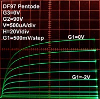


The following plots superimpose pentode operation with G3 bias and Tetrode operation.
G3=0V or 7.4V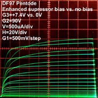 G3=0V or 90V
The effect of the small +7.4V bias at the suppressor grid was particularly interesting, considering that much of the effort in pentode and beam tetrode design during the tube era concentrated around the low voltage operation region; remember the KT-"kinkless tetrode" English line of tubes, with the KT88 being one of the most famous?
Larger versions of these plots are attached.
Regards/Cumprimentos,
-Joe
Attachments:- DF97_curves_pentode-vs-tetrode_2 (111 KB)
- DF97_curves_pentode-vs-tetrode_3 (117 KB)
- DF97_curves_pentode-vs-tetrode_1 (118 KB)
- DF97_curves_pentode-vs-tetrode_23 (135 KB)
- DF97_curves_pentode-vs-tetrode_12 (138 KB)
To thank the Author because you find the post helpful or well done.
DC90 triode Grid Conduction
One of the more interesting aspects of this radio is the extensive use of forward (positive) grid bias. It is used in the local oscillator for the positive half cycles, it is used at the IF stages for volume control with forward bias conduction, and it is used in the Anode bend detector stage.
I explored forward bias in the 3A5 curves shown above. I decided to look further into the forward bias operation of the european DC90 triode. This time I expanded the sweep into the heavy forward grid bias that is expected at the local oscilator stage during the positive half cycles.
First, the classic set of plate curves, but expanded to include forward grid bias. This curve family is often seen in data sheets of tubes meant for class C operation. These data shees usually include a superimposed plot of grid conduction. My Tektronix 575 curve tracer does not have this capability, so the grid conduction cuves were done differently.
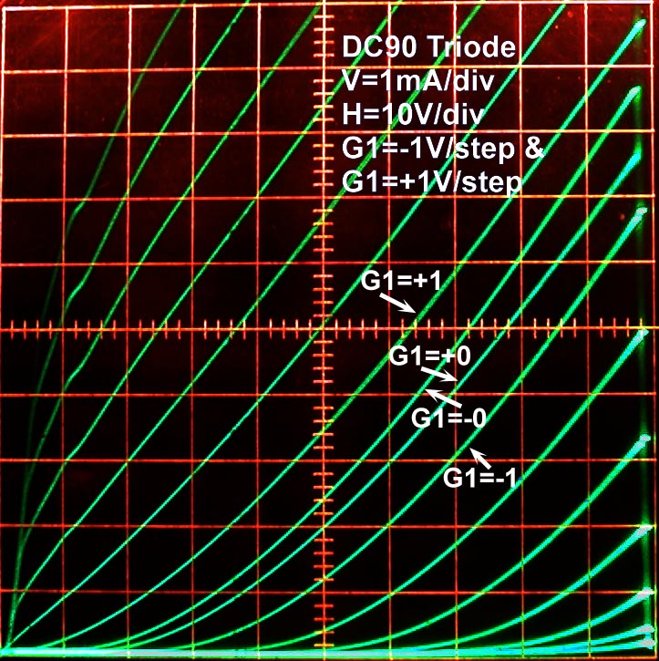
Second, Grid conduction voltage/current sweeps for small and large grid voltages:


The low voltage plot on the left makes it clear that the grid will not start conducting until the grid voltage reaches 1.5-2V. This part is most relevant to keep the detector from loading the IF transformer driving it.
The higher voltage plot on the right shows how much current the grid draws with large positive excursions when the plate voltage high. This plot is most relevant for the operation of the volume control in the IF stages and in the large positive swings that are expected at the grid of the local oscillator.
So the plate does a very good job of "steeling" most of the grid conduction current. The concept of forward bias concution in a grid depends strongly on the voltages of the other tube elements. This reminds me of bipolar transistor operation, where the collector voltage usually sweeps way more than 99% of the forward biased base current, but the grid current is much more dependent on plate voltage, than base current is on collector voltage.
Regards,
-Joe
p.s.: The pictures on this post have high resolution, but I used a feature I just found in the posting editor, where the size that is shown is smaller. If you right-click and save these photos, you should get about 750x750pixel size.
To thank the Author because you find the post helpful or well done.
The power supply...finally
Hello Joe,
Finally i did the power supply, and following your advice, i change the schematic to have various voltages.
The power supply have:
For the filaments: 4 volts
Negative voltage (adjustable): 0 to 25 volts
Other voltages:
One 30 Volts or 40 Volts
One 67,5 Volts or 80 Volts
One 90 Volts or 100 Volts
One 110 Volts or 120 Volts
I can select, change some "bridges".
Regards
Attachments:
- Power Supply for Battery Radi (62 KB)
To thank the Author because you find the post helpful or well done.
Versatile supply.
Hello Carlos,
Good to hear your progress. This supply seems quite versatile in it's ability to provide a very wide range of voltages and many separate outputs. The zener diodes provide a lower impedance alternative to simple resistors. I had not seen this approach in supply design for a 1920's battery radio, and it seems very well suited.
The most important voltage is the filament voltage, because it is the only voltage that could easily kill an 1920's tube with a thoriated filament. I killed an American UX199 TRIODE this way. It was not a great loss because that triode was already fairly weak. The more modern coated cathode types I discussed earlyer in this thread, seem to take a short over-voltage at the filament without immediate destruction.
When wiring things around, the connection to be careful with, is the control grid connection. A momentary connection of the control grid to a stiff high voltage could do damage.
This makes me think that a current limiting high voltage depletion mosfet from Supertex, like the LND150, or another size with the appropriate current rating, would make the supply short-circuit proof such that accidentally tying a control grid to +90V may not be disastrous. But a resistor with a good amount of voltage dropped accross it is also a good current limit. Another good current limit could be provided by a small 15W 220V lightbulb. The 15W bulb will draw 68mA from 220Vac, and perhaps 25mA with a 50V drop. It will be impossible to kill the bulb with a short to ground, if your unregulated supply is 170VDC, and the zener stack is 120V. I got this light bulb current estimate from measurements of a Rustika Lightbulb that creates RF emissions. The specific file for filament currents is Rustika_Filament_Temperature.pdf This file has data for a 60W bulb, so I scaled the data for 15W.
The light bulb also serves as a visual indicator when the current drawn is greater than the bias current of the zeners, or when there is a short.
Keep in mind that the zeners will dissipate a fair amount of heat as a group. Even with just 50mA through the 29 zerner stack, you have about 7W of dissipation, or 1/4Watt per diode. Just keeping the diodes spread out may be enough to keep them from getting too hot to touch. Glueing the diodes to an aluminum box may serve as a good heat sink.
Keeping the supply filter caps in the 0.01uF to 0.1uF range also reduces the changes of damage from high current spikes in the case of an accidental short.
Does your choice for 4V at the filament supply mean you have some tube types in mind?
Good luck with your efforts,
-Joe
To thank the Author because you find the post helpful or well done.