MW Modulator from Autoscan FM radio
MW Modulator from Autoscan FM radio
Below is a rough translation of Mittelwellen-Modulator und Scanradio by Gerhard Heigl
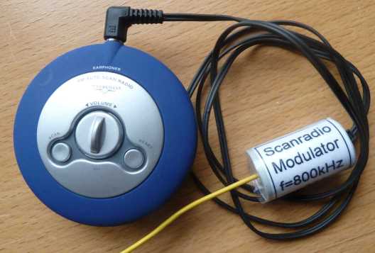
A really simple AM modulator (transmitter) that allows listening to all the available FM stations on medium wave. The design is particularly well suited for beginners. Few components, no coils and therefore no adjustment problems. This unit is designed for use with cheap auto scanning radios. The AM Modulator operating voltage comes from the headphone jack of the radio scan. The 220 Ω resistor is to povide a load.

The supply voltage of the modulator is about 1V since the autoscan FM Radio uses 2 x 1.5V batteries. Since this voltage varies with the audio, the generated high frequency is also amplitude modulated. The high frequency is generated with a resonator in conjunction with the transistor. The sample device was fitted with a resonator 800kHz. Any other resonator whose frequency in the medium wave range can be used.


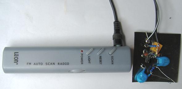
Construction: The circuit can be constructed in a short time on a small piece of breadboard. The print pattern (image) has the dimensions 23 x 15mm. The 1nF capacitor was deliberately chosen with a high operating voltage, so there are no nasty surprises, should the modulator output (RF out) to come into contact with high voltage.
Operation: The cable scan radio - modulator should be at least 50cm (20") long, because this cable acts as an FM antenna for the radio scan. Some radios the jack tip is +ve and some it's -ve. If the polarity is wrong the RF signal might be very weak or missing.
The Modulator can connect direct to the tube radio aerial socket or for a portable radios it is sufficient to lay it next to the radio. In some cases a few loops of wire on the Modulator can couple to the Radio. The modulation depth can be adjusted with the volume control on the FM auto scan radio.
The modulator was tested with three different auto scan radios, with an AM transistor portable receiver and with a tube radio.
To thank the Author because you find the post helpful or well done.
Does it work for me?
On the "Scan Radio" I tested the "tip" of the connection was -ve and the "barrel"(mono jack) or "ring" of stereo jack was +ve, with 220 Ohms load 0.95V was measured, with a Stereo Jack the "barrel" was "no connection.
I did not have a MW band resonator.
So I have 4 choices:
- A 500KHz resonator. The 2nd harmonic might be strong.
- A Crystal (But I have various between 1.8MHz and 30MHz, none on MW or LW)
- A tuning capacitor and coil from a €2 AM Radio
- A 455KHz IF filter from a €2 AM Radio.
I chose (1) and used a 2N3904 transistor (I have the BC548) as it's more familar to US readers :-)
I built the circuit "dead bug" style laid out close to schematic soldered to a scrap of coffee tin with a pair of 1kV 2.2nF capacitors connected via 1M Ohm on the output and ground. They were from a scrap PSU.

It took less than 10 minutes.
I hooked up my HP141T spectrum analyser with 110MHz plug in on 10MHz range and indeed the circuit was working at once powered from the auto-scan FM Radio. The 1MHz was about 10dB below the 500kHz. Still plenty of MW signal.
Do not connect an aerial if you build one with 500 KHz. Connect direct or use a small loop.
The signal fully closed the magic eye on my Pye 39 JH/E only connecting the aerial and not the earth. An attenuator may be needed for direct connection.
Quite low volume setting was required for adequate and undistorted modulation.
Conclusion:
Yes, it works for me. My €2 (£1.50 or $3 roughly) autoscan FM radio is the same single chip in most of these. It can work OK, but poor soldering is sometimes an issue in these (pure tin solder and no flux?). The quality didn't seem as good as my Russian Rod Pentode AM generator, but could be the Autoscan radio.
Things to try:
- Using a 455kHz filter off a cheap radio and tuning to harmonic 910KHz
- Using the coil + tuning cap of the cheap radio
- A crystal for SW.
- Using 1.2V by 2 x diodes and resistor from a USB port and driving with PC line out.
It's very simple and quick to make. The only part you might not have to hand is a suitable resonator, but as I have shown you don't actually need one in the MW band.
Thank you Gerhard Heigl!
To thank the Author because you find the post helpful or well done.
Supplement
Gerhard Heigl continues:
Supplement
I've built a second modulator, with a reversed supply voltage, to suit +ve earth autoscan FM radio sets. This modulator didn't work. Cause: The capacity of 100pF capacitor right of the transistor was too small. With 150pF, the modulator is working properly. The modulator can be equipped with an npn (-ve earth) or pnp (+ve earth) transistor, to suit the polarity of the earphone socket connection.

An amended PCB design is available, size 33 x 15mm. The width of 15mm is maintained so that the PCB can fit in an M20 electrical conduit (42mm length). The PCB was made by this method here (German).


[Editor Notes:
However as long as the earphone connections are the correct polarity, it really doesn't matter if PNP or NPN is used as only the output of the modulator connects to an Earth.
If your country doesn't permit low power AM transmitters, then don't connect an aerial, but use a small loop to couple to Ferrite Rod, Loop Frame aerial or an attenuator (2 resistors) to connect directly to Aerial and Earth sockets]
To thank the Author because you find the post helpful or well done.
500KHz Resonator
The 500KHz resonator is common on old video recorders and remotes. Since the harmonics are 1MHz and 1.5MHz this is quite good to calibrate scale pointer and/or RF/LO trimming/tracking capacitors as it gives roughly a mid point and end point on the scale. On old Radio sets this is 300m and 200m on the dial.
About 1.5m of wire loosely coiled and taped about 6cm diameter just connected at one end to the modulator coupled fine with the loop aerial on my Ever Ready Personal B
The correct audio level on the Auto-scan FM Radio is quite low.
On some tube portable sets it could be possible to add the two parts inside with power, reset and scan switches poked through a grill and no modification to the battery set at all.
To thank the Author because you find the post helpful or well done.