telefunken: 2194; Concertino -- UKW not working
? telefunken: 2194; Concertino -- UKW not working
I am restoring a Telefunken Concertino 2194. I have replaced all the paper capacitors and a couple of resistors that were out of tolerance. The radio works well on all the AM bands - LW, MW, and KW -- and sounds great. FM (or UKW), however, is not working. It does receive one station, extremely weak, volume has to be at maximum to hear it. This station is just outside the FM band the radio should receive -- 101.0 MHz.
All the voltages are okay. I have checked the waveband keyboard switches and they are okay. I have tried known good tubes (valves) -- ECC85, EF89 (2x), ECH81, and EABC80 with no change.
I have made some DC resistance checks through the FM front end section with the ECC85 removed to verify the resistors. They are okay with the exception of W604 which should be 33k and I measure 21k. But I am not sure how to open the front end section, so nothing has been changed (or cleaned for that matter).
I am hoping for some suggestions on where to procede. Or perhaps notes on how to open and service the FM front end. Has anyone had similar problems with this model? Any guidance would be appreciated. Regards, Jim
To thank the Author because you find the post helpful or well done.
? Maybe a solution

Hello Jim.
If you want,read here. Maybe a solution for parts of your problem.
post # 4,8,10,12,14,16, and 18.
8 is important.
hans m. knoll
To thank the Author because you find the post helpful or well done.
Great help
Thanks Hans. That link will be a big help. First, I now know how to open the RF section. Second, it gives lots of help in understanding how it works and what is important. Much appreciated.
Jim
To thank the Author because you find the post helpful or well done.
? whe make if whe can
Hello Jim
Important is: the cores inside the FM-Box being moved via Dial?
Post 8, Local Osc. works ? Without this, no reception is doing.
Your Signal at 101 can bee something e.g. Overloading the RF- Stage.
hans
To thank the Author because you find the post helpful or well done.
? Cores moving okay
Hi Hans,
With the information in the thread you provided I was able to remove and open the FM front end. The good news: the cores are okay and moving properly. So far I have been able to only inspect the unit. Everything looks okay. I did test the diode. It is okay. The resistor I was concerned about is really a 22k resistor. The schematic shows a 33k resistor there. Perhaps this resistor (W604, the bias resistor for the anode of the oscillator) is selected during manufacturing.
Based on your explanation in the other thread, I suspect the oscillator is not working and the radio station I hear is due to the mixing of two stations. The schematic shows that both the RF amplifier and the oscillator should draw 12.7 mA. I will verify that.
The schematic also shows a switch S7 that is part of the FM tuning knob. What is the function of this?
Jim
To thank the Author because you find the post helpful or well done.
? S7 -- AFC ciircuit
Hans,
I read further in the other thread and now realize that S7 must be part of the AFC circuit. But I'm still uncertain what it does?
To thank the Author because you find the post helpful or well done.
? Local Osc. testing
Hello Jim.
You must go to post 8 an realise the Measuments DC- Volt on Testpoint on FM-Box
or this test
If you not understand what's do to? Let me now.
It's abolute important.
hans
- measurment of local oscillator (56 KB)
To thank the Author because you find the post helpful or well done.
Will do
I will try these tests this evening. Thanks for the help.
Jim
To thank the Author because you find the post helpful or well done.
? RF Front end okay
Hans,
I performed the test you requested. At the test point I measure -3.3 vdc. Looking at the signal on the test point with an oscilloscope, I see a sine wave from 0.0 vdc to -5.6 vdc at 11.02 MHz. I think this is okay? Any thoughts?
Jim
To thank the Author because you find the post helpful or well done.
? Next stepp
To thank the Author because you find the post helpful or well done.
? Measurements made
Per your request, here is what I measured:
- Adding a 3900 pF capacitor in parallel to C610 had no effect. Oscillations still present.
- Opening W602 is too difficult, so I did not do this.
- Adding 220 pF in parallel to C616 (130 pF) stopped the oscillations. Voltage at the test point is -0.56 vdc. Anode voltage, 72 vdc (no oscillations). Voltage across W602 (150 ohm cathode resistor of 1st triode) is 1.34 vdc with pin 2 of the RF box open (no connection), with it connected the voltage is 0.97 vdc. Anode voltage of 1st triode is 163.4 vdc. Pin 5 of the RF box is 170.0 vdc.
All of these tests were done with the RF box removed from the chassis. RF box assembly is open. Jumper wires are used to connect HT (170 vdc), 6.3 vac, and earth (ground).
Any suggestions?
Regards, Jim
To thank the Author because you find the post helpful or well done.
? last order ;-)
To thank the Author because you find the post helpful or well done.
Thanks for the help
Hans,
I appreciate all the help you have given. I will also check the sources you supplied. Many thanks.
Jim
To thank the Author because you find the post helpful or well done.
? Oscillation due to O-scope?
Hans,
I suspect the 11 MHz oscillation may be due to the oscilloscope (O-scope) probe. I put the assembly back in the box for proper shielding. I also mounted the box back on the chassis to provide a proper ground (earth). I connected HT and 6.3 vac. I then measured the voltage at the test point through a 100K ohm resistor using a DC voltmeter (per other thread). I measured -2.95 vdc. Still using the 100K resistor, I measure the same with the O-scope with no oscillation. But without the 100K resistor and probe directly on the test point, it oscillates at 11 MHz.
Still, I do not see any oscillations on this test point in the 100 MHz range.
I am tempted to re-connect all wires to see if anything has changed.
Regards, Jim
To thank the Author because you find the post helpful or well done.
? Final ?
Hello Jim.
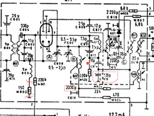
As an installation you can find a picture with components.
When in a red way marks, are to 100 % participated in the failure of the oscillator. As being green-marked, only the 2x 7,5 pF. The 11 pF is actually in function. Otherwise the stage would not have oscillated on 10,7 Mcs.
What i think is: the Diode ist wrong! O.K. you think no!
EDIT: More.
Uses Portable radio, tune the VHF box on lower end (88 Mcs)
Bring the rod antenna of the portable near to the ECC85 bulb and search at 88 + 10,7= 98,7 for a strong carrier.
If an local VHF Carrier is busy there. Move the Box a little bit higher.
You can find that in German here.
Switch the VHF- Box off and on to test what Carrier you receive.
Booth, that and use off VTM and 1 Meg. i have recommendet long bevor.( post 7, above) I am sorry, english ist not my language!
I wish you a lot of success .
Hans
To thank the Author because you find the post helpful or well done.
Success!
Hans,
I have determined the faulty component, C616 - 130 pF capacitor. I did a number of things to simplify the circuit.
- I soldered pins to all the input and output signals from the FM box. This made it simple to make and break all connections to the FM box. I do not like to use jumper wires for high frequency circuits due to the uncertainty they add in terms of inductance and capacitance.
- I disconnected the cathode resistor, W602 - 150 ohm, to eliminate the first triode as the source of the 11 MHz oscillations.
- I used the schematic you presented in the other thread which showed the schematic of the FM box from a Gavotte 9. This radio has a nearly identical FM box, but does not have the AFC circuit. This eliminates the diode, GR601, and capacitors C615 and C619 (both 2200 pF). I temporarily modified my FM box to the Gavotte 9 FM box. 11 MHz oscillations still present.
- Finally, I removed C616 - 130 pF capacitor (measured 80 pF) and installed a 180 pF (It is what I have on hand.). That did it. FM box now oscillates from about 98 MHz to 111 MHz.
I still have to undo the other modifications I did, but I feel certain it will continue to work. Thanks for all of your suggestions, you have been most helpful, and I would not have gotten there without your assistance.
Regards, Jim
To thank the Author because you find the post helpful or well done.