The Cockaday Audion
The Cockaday Audion

The Cockaday Audion
The Cockaday Receiver, named after it's inventor L.M. Cockaday is probably one of the most intriguing regenerative receiver circuits of the 1920's - and few receivers were so controversially discussed in the radio community until this day. The reason for these controversial discussions is in the fact that Cockaday used a unique regeneration control method that in this form is not found in any other receivers from this era and beyond. While standard regenerative receivers employ feedback control e.g. from the plate circuit to the grid tank circuit, approaching the ideal point of operation just below the onset of oscillation from the non-oscillating state of the audion, Cockaday receivers work in inverse fashion. An "idling" Cockaday audion is in the oscillating state, and the correct point of operation just below the onset of oscillations is established by extraction energy from the tank-circuit by means of a parasitic damping circuit. This method of regeneration control leads to a rather unusual behaviour compared to standard regenerative receivers.
In his days, Cockaday advertised the reception sensitivity and demodulation quality of his receiver as being far superior to standard regeneration receivers - but only if his original "Cockaday Precision Coil" set was used. In retrospect one might wonder, whether in comparison to other radio sets of the mid-twenties Cockaday's claim was justified, or whether this was just a clever marketing trick. So we started asking ourselves whether there was a possibilty to verify his claim by measuring the operational parameters of one of his sets using modern equipment. Unfortunately only few of these receivers still exist in original unmodified condition, and we found it difficult to persuade the owners to run conclusive measurements on their sets that would lift the veil of mystery shrouding the Cockaday reveivers. As a matter of fact we had feedback from only one fellow collector, Joerg Sigg, who provided the results of Q-factor measurements on his set.
Finally we gave up waiting for more information from other Cockaday set owners, and decided to build our own, "as-close-as-possible" replica of a Cockaday receiver following the instructions found in the original literature. The measurements run on this replica yielded a number of intriguing results, now allowing a much deeper understanding of the function and operating behaviour of this unusal type of radio receiver - but they also raised a number of interesting new questions, in particular concerning the stabilizer - tuning circuit interaction.
In an attempt to answer these questions, our Cockaday studies were complemented by running a number of LT-Spice network simulation calculations. An arrangement of 4 coils is a linear network, and can easily can be analyzed by LT-Spice. But although these calculations yielded interesting information on the mutual influence of the Cockady coils, the measurements made on our Cockaday replica seemed to contradict these results. The reason for this discrepancy was finally found in the fact that the calculations did not account for the properties of the active component of the Cockaday tuner: an Ar-gas-filled tube.("Gassy audion tube UX200").
In this way, the comparison of measured and calculated coil parameters and resonance curves gave the decisive clue on the primarily underestimated, but in reality substantial influence of the strongly non-linear characteristics of the gassy audion tube on the Cockaday receiver performance.
This report we will first recapitulate the functioning principle of the "original" and the "improved" Cockady 4-circuit tuner, followed by a detailed description of its essential components, the "Cockady Precision Coil" set and the "gassy audion tube".
We then pass on to the practical setup of our replica, summarize the results of measurements run on this replica, and the results of our simulation calculations, and finally comment on the possibility of synchroneous demodulation.
Readers who are interested in getting more original information on the setup of a Cockaday receiver are invited to study the latest reprint of one of his books:
This publication has been reprinted in 1992, and has the ISBN number 1-55918-095-1.
Cockaday's Original 4-Circuit Tuner
Principially, the Cockaday audion is an improved version of De Forest's original "Ultraudion" circuit.
.png)
De Forest controlled plate -> grid feedback using a variable grid condenser C2. But due to direct feedback from plate to grid, oscillation had been hard to control in ultraudions.
The essential merit of Cockaday consisted in introducing an extra circuit, a so called "stabilizer" circuit, allowing to extract energy from the main tank (L2, C1 in the De Forest Ultraudion), and by doing so reduce the oscillation amplitude to a minimum.
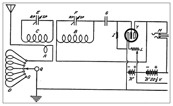
Original Cockaday Tuner
- The main tank circuit, i.e. the circuit that selects the reception frequency, consists of Coil "B" and variable cap "F", and is positioned between grid and plate of the triode tube "Y", like in the "ultraudion". Capacitor "G" insulates the plate potential from the grid potential.
- A damping circuit ("stabilizer circuit" in Cockaday's nomenclature) consisting of coil "C" and variable cap "E" is magnetically coupled to the main tank circuit. Depending on the setting of the variable capacitor "E" the damping circuit will extract more or less energy from the main tank circuit and thus allow to set the correct operation point close to oscillation onset.
- The antenna signal is coupled to the damping circuit using a 1-turn coil "A". Selecting the most suitable tap of coil "D" allowed to optimise antenna impedance matching.
- The coupling from coil "D" to the other coils is not so obvious, and will be discussed below.
Cockaday's Improved 4-Circuit Tuner
But apparently, a number of customers was not satisfied with the operating performance of the "Original Cockaday Tuner". Cockaday reported on negative feedback from radio amateurs, who had build the receiver following his prescription: Some of the built receivers "did not oscillate freely, while other sets were oscillating too much".
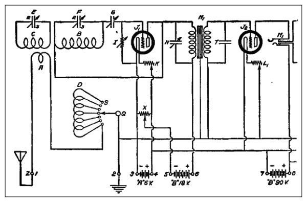
Cockaday reacted by devising an "Improved 4-Circuit Tuner" (on pp. 67 - 79).
Original Cockaday Improved Cockaday
For easier comparison we show both diagrams next to eachother.
The basic coil and resonant circuit setup stayed unchanged. However, one can see that in the "improved version" Cockaday introduced some important changes that helped avoiding the shortcomings of the original circuit layout:
- The most important improvement is the reduction of the "B" battery voltage 22.5V to 18V.
However, Cockaday did not point out this but only commented in "Practical Pointers" (on p. 57):
"Gassy tubes as used for detectors function at plate voltages between 16.5 volts and 22.5 volts; usually they function best at a plate potential of about 18 volts."
- A potentiometer "X" was introduced across the filament battery "A". By connecting the negative pole of the "B" battery to the tap of this potentiometer one could now vary the average plate voltage even below the ionization threshold of Ar-gas.
- The remaining newly introduced components like the variable grid condenser "G", the grid rheostat "I" and the condenser "H" at the plate of the tube "J1" (UX200) were found to have minor influence on the behavior of the Cockaday receiver and will not be further discussed.
The Cockaday Precision Coil
The heart of every Cockaday receiver is the "Cockaday Precision Coil", a special arrangement of 4 individual coils as shown in this original advertisement of 1925.
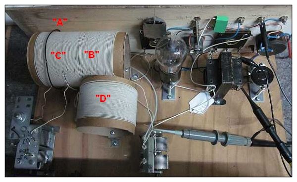
An original drawing of this unusual coil arrangement is shown in the following picture (A picture with higher resolution will be shown later in the context of our Cockaday replica setup)

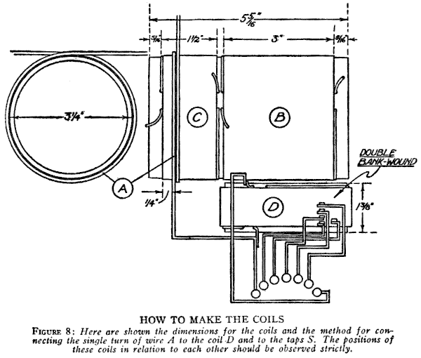
As already shown in the circuit diagrams of the original and improved version, the Cockaday Precision Coil consists of a main tank coil "B", a stabilizer coil "C", an antenna matching coil "D" which is perpendicular to the main tank coil "B", and a single turn "A", the antenna coil, wound over the stabilizer coil "C". The advert does not show the 1-turn coil "A".
While "A", "B" and "C" are coaxial, coil "D" is perpendicular to the others. As will be detailed later, Cockaday's drawing specifies all dimensions, wire gauges and positions - apart from the exact position of coil "D". We will see that incorrect positioning of coil "D" leads to distortions in the main circuit resonance curve.
Soft Detector Tube

The key component, decisively influencing the behaviour of the Cockaday receiver is the triode tube "Y". It is of vital importance for the understanding of the operational behaviour of Cockaday receivers that these did not use high vacuum tubes, but "soft" Argon gas filled tubes (abbreviated "Ar" or in some publications "A"). Tubes used in Cockaday's setup were the UV200 or its electrical equivalent UX200. The recommended plate voltage is 15 - 25 volts, depending on the actual gas pressure of the tube in use.
As shown in the schematic above, the first version of Cockaday's 4-circuit tuner (on pp. 45 - 56) used a filament battery "A", in combination with a rheostat "L" that allowed adjusting the actual filament voltage/current.
In contrast, the plate voltage in his original design was fixed, using a battery "B" of 22.5V. Apparently Cockaday at some point understood that this fixed "B" voltage posed a problem, since the value was superior to the ionization voltage of Argon gas: 15.76V. Using this high plate voltage, electrons ionized Ar-atoms causing bipolar charge flow: fast electrons to plate - slow Ar-ions to filament. This entailed current shape distortion and deteriorated the performance of the Cockaday receiver.
Measured on a curve tracer, the UX200 valve used in our Cockaday replica setup (Thanks to Joe Sousa) shows the following characteristics: The left hand diagram shows the usable region with plate currents less than 100μA.


- Horizontal axis: plate voltage; left: 2 V/division; right: 5 V/division
- Vertical axis: plate current; left: 20 μA/division; right: 100 μA/division
- Grid voltage; left: -0.5 V/step; right: -1 V/step
- Filament voltage is 5 V
The right hand diagram shows a steep increase in plate current beyond the ionization voltage of the Ar gas.
Examples of the influence of gas on the characteristics of a tube are also found in "Morecroft, J. H., Pinto, A., Curry, W.A.: Principles of Radio Communication, 3rd. ed., Wiley, 1933".


An essential feature of the gas filled tubes is the extremely low transconductance of significantly less than 0,1mA/V = 100 µmhos. Testing our UX200 we found a value of approx. 38 µmhos = 0,038mA/V. A slightly higher value of about 50 µmhos = 0,050mA/V can be extracted from Morecroft's Fig. 38.
- Only because of this small transconductance of gassy tubes it was possible to control the oscillations in a De Forest Ultraudion an in a Cockaday receiver, i.e. in receivers with direct "plate → grid" feedback. Modern triodes with much higher transconductance are inapt for this application, since it will be impossible to stop them from oscillating.
So it is evident how much the performance of the Cockaday receiver will be affected by the actual characteristic of the soft valve used.
Practical setup of our COCKADAY replica
Unfortunately, we had no access to an original Cockaday set - neither basic nor improved - to do the evisaged measurements. It was therefore decided to build up our own Cockaday radio following the instructions given in the available liturature.
But fortunately we could get hold of an UX200 tube (Thanks to Joe Sousa) whose operation then showed how sensitive this tube reacts on changes of the "B" voltage. The experiments confirmed that the most important factors in Cockaday's "improvements" were the reduction of the "B" voltage, and the possibility of fine tunig the plate voltage by means of the rheostat "X".
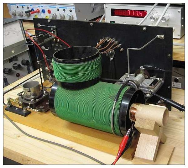
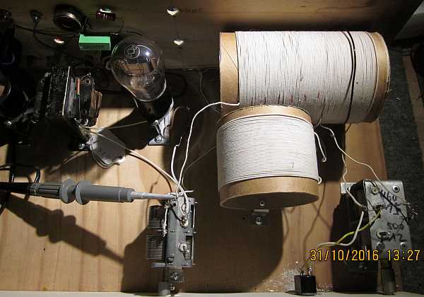
Here a few pictures of our initial setup: (Modifications will follow below.)
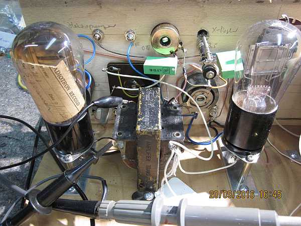
The photo shows the UX200 (audion) on the right hand side, and the UX201-A (AF amplifier) on the left hand side. With respect to the original Cockaday proposal, the circuitry has been modified to some minor extent:
Both, "A" and "B" batteries were replaced by mains DC sources.To eliminate distortions from mains, two (green) condensers (4.7 μF) were necessary.
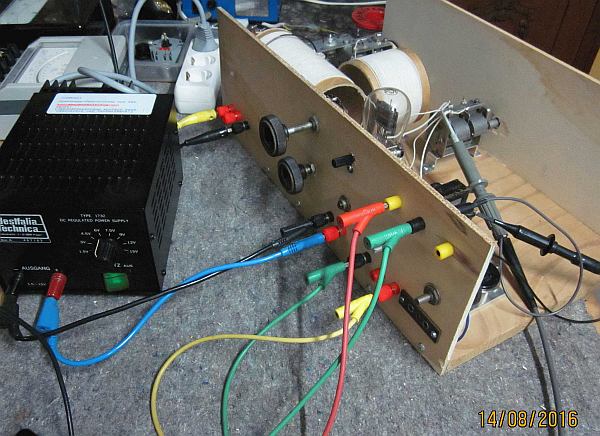
The next picture shows the front panel of our setup, with the 6V stabilised power supply replacing the "A" battery.
The "A", "B", "C", and "D" coils, which are the heart of the Cockaday receiver, were constructed according to the descripton, given in Cockaday's publication - with the only exception of the "D" coil, which was neither tapped nor "bank wound".
The "D" coil is surrounded by a certain mystery, and when we assembled our Cockaday, we didn't really know exactly where to put it. As can be read in the figure caption above, Cockaday emphasizes:
"The positions of these coils in relation to each other should be observed strictly."
The surprising fact is that indeed, all positions, diameters, and wire gauges are exactly stated in Cockaday's drawing. But there is one exception: The exact position of coil "D" relative to the others. Did Cockaday conceal this point intentially because it has fundamental importance for the performance of his receiver? In this case, amateurs refraining from the purchase of his original "Cockaday Precision Coil" would have got unsatisfactory results - unless by accident they found the correct "D" coil position. Somehow this assumtion does not seem logical. If the drawing in Figure 8 above is approximately to scale, every amateur could have easily calculated the coil "D" position by using the coil diameters as a reference dimension.
Or is the position of this coil arbitrary, because "D" is positioned perpendicularly to the other coils? So Cockaday did not state the position because it had no influence? But if Cockday had really wanted to avoid magnetic field coupling between coil "D" and the others, why did he not simply increase the distance between the coils. There could be two reasons for that: (i) He wanted to keep the whole coil assembly as compact as possible - which in a way sounds logical or (ii) he had a divine revelation and anticipated (he had no spectrum analyser to measure this effect) that incorrect positioning of coil "D" would have a distorting influence on the resonance curve of the main circuit.
This brings us to the point of "Orthogonality".
Orthogonality
A popular opinion states that two coils, which are in perpendicular position do not influence each other. But are all coils "A", "B", and "C" really "orthogonal" to coil "D"? Obviously, they are not beause "orthogonal" includes not only "perpendicular", but also "symmetrical" to all coils. Only then the magnetic flux of coil "D" will be (completely) compensated or cancelled in the other coils, and vice versa.
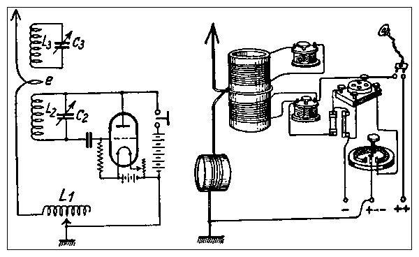 However, the Cockaday arrangement of the 4 coils often was misunderstood, like in a contemporary book on radio techiques. (Wigge, H.: Rundfunktechisches Handbuch, vol. 1, Krayn, Berlin, 1925)
In the intepretation of Wigge, coil "D" (L1) indeed does not couple to coils "B" (L2) and "C" (L3) at all. The only coupling to the antenna here is via coil "A" (e), while coil "D" (L1) only serves for matching the antenna. (Furthermore, no means for fine tunig the "B" voltage is proposed.)
Cockaday interpreted by Wigge
Having understood that due to a lack of orthogonality there must be a certain degree of coupling between coil "D" and the others, the task was now to find out what influence its position has - and on which parameter. Rather than playing around with the coil "D" position in our setup, not really knowing what exactly to look for, we decided to look for the solution by running LT-Spice network simulation calculations.
LT-Spice Simulations
In our LT-Spice simulation the Cockaday's 4 coil arrangement was modeled as shown below. Some of the coupling factors could easily be measured, while others could only approximately be determined. To find out their proper values some iteration loops had to be run, but then we had the solution. (Thanks are due to Joe Sousa for his support.)
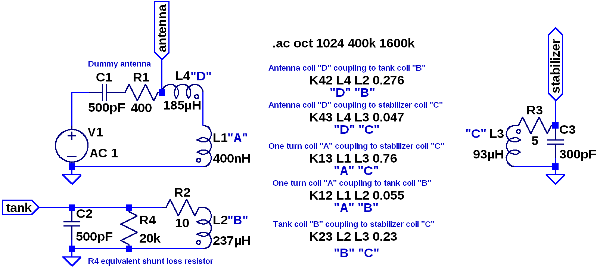
The LT-Spice analysis was run for four different coupling scenarios between coil "D" and the remaining coils:
- Antenna coil "D" does not couple to any other coil. Only the single turn coil "A" couples to coils "B" and "C"
- Antenna coil "D" is coupling to coil "B" only, but not to coil "C". Coupling of coil "A" remains unchanged.
- Antenna coil "D" is coupling to coil "C" only, but not to coil "B". Coupling of coil "A" remains unchanged.
- Antenna coil "D" couples to coils "B" and "C". Coupling of coil "A" remains unchanged. The coupling factor KDB (K42) is varied until a perfect compensation of the unwanted peak in the resonance curve of the main tank ("B", "F") is realized.
The diagrams below show the resonance curve of the main tank ("B" (L2), "F" (C2)) for these four scenarios. The frequency spectrum covers the band 0.4 - 1.6 MHz.


case 1) "D" does not couple at all case 2) "D" couples to "B" only
Left hand peak: main tank resonance-> 460kHz Left hand peak: main tank resonance-> 447kHz
Right hand peak: stabilizer resonance -> 988kHz Right hand peak: stabilizer resonance -> 990kHz
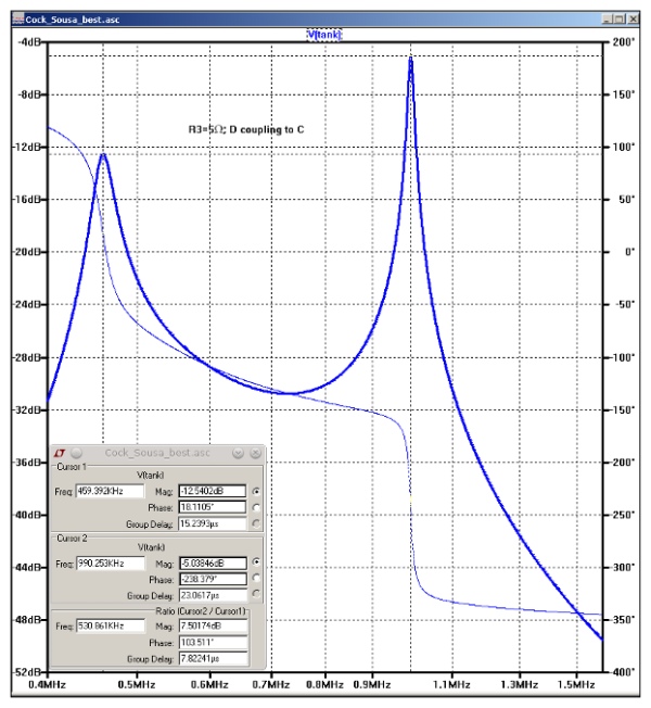
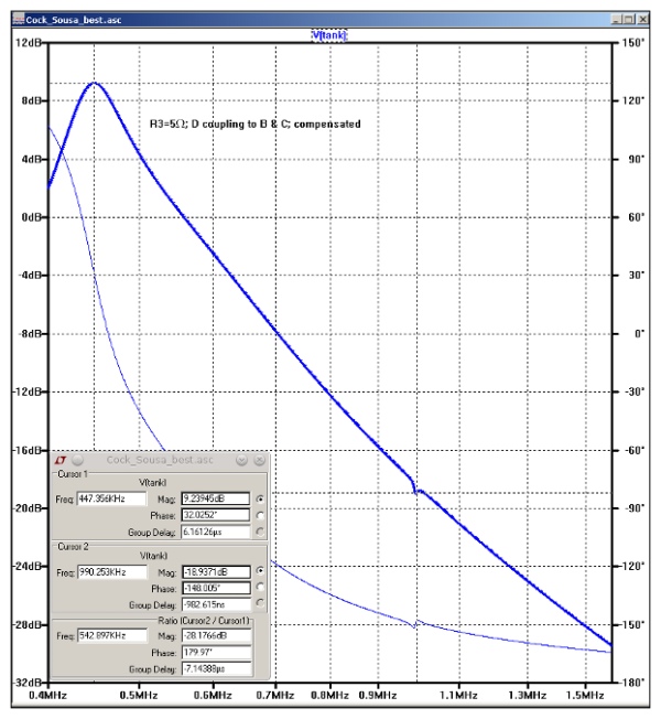
case 3) "D" couples to "C" only case 4) "D" couples to "C" and "B"
Left hand peak: main tank resonance-> 459kHz Left hand peak: main tank resonance-> 447kHz
Right hand peak: stabilizer resonance -> 990kHz Right hand "peak": stabilizer resonance -> 990kHz
The most interesting and unexpected result is seen in the diagram of case 4:
In this case, where the antenna coil "D" couples into both, the main tank coil "B" and the stabilizer coil "C", the influence of the stabilizer circuit ("C, "E") on the main tank resonance curve disappears, which is due clearly to a compensation effect. This is obviousely the correct alignment, since when tuning the stabilizer, one does not want to detune the main tank circuit frequency response curve, but only attenuate its oscillation.
- Consequently it is wrong to assume that Cockaday placed the antenna Coil "D" in a position where it does not couple to coils "B" and "C"! On the contrary, the coupling must be well chosen to make sure that a variation of the stabilizer circuit does not detune the main tank circuit!
The LT-Spice simulations suggested that not only a unique set of parameters gives this result, but several other sets of parameters could most probably also lead to the same result. In practice this means that it is allways possible to get the desired result by fiddling with the values of potentiometers and condensers.
These LT-Spice simulations are described in the appended paper. [see attachment "Theory of Cockaday Audion"] The ivestigations in this paper do not include the influence of the soft audion valve.
Experimental Results
Having understood the role of coil "D", we could now optimise its position relative to coils "A", "B" and "C" in our experimental setup. This was done iteratively:
- Set the stabilizer circuit resonance to minimum disturbance of the main tank resonance curve and change the position of coil "D" until the disturbance of the main tank is further reduced.
- Now tune the stabilizer circuit resonance until the disturbance of the main tank is further reduced.
- Repeate this procedure until no better reduction is possible.
- This procedure has to be done for a frequency at the upper end and at the lower end of the AM band.
- Find the final position of coil "D" when for both frequencies a minimum disturbance of the main tank resonance curve is achieved.
Two frequency response curves of our main tank circuit were run:
(i) Main tank resonance frequency set to f = 1.629 MHz. Stabilizer tuned to a frequency above main tank resonance.


Coil "D" in wrong position Coil "D" in orthogonal position
(ii) Main tank resonance frequency 529.625 kHz. Stabilizer tuned to a frequency above main tank resonance.
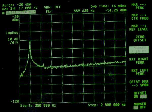
Coil "D" in wrong position Coil "D" in orthogonal position
This means that the measurements carried out on our Cockaday setup confirmed the results obtained from the LT-Spice simulation calculations:
We could actually identify a coil "D" position of the stabilizer circuit in which the resonance curve of the main tank circuit "B" is only very little influenced by the stabilizer circuit - but quite honestly, this needed some fiddling.
Effect of the stabilizer circuit
The question one is confronted with now is obviously the following:
If the stabilizer circuit - with coil "D" in (nearly) orthogonal position - has no significant effect on the resonance curve of the main tank, what effect does it have at all? Couldn't the stabilizer circuit be omitted?
The answer is "NO" since one has to distiguish beween two effects on the main tank circuit:
- The transformation of the reactance component of the stabilizer circuit that leads to a change of the resonance frequency in the main tank. This is the influence we were talking about in the previous section. Ideally, this effect should be small, to make sure the main tank ircuit is not detuned when the stabilizer setting is changed.
- The transformation of the ohmic component of the stabilizer tank gives an increase of losses and thus damping in the main tank circuit. This is the way of feedback is controlled in a Cockaday audion as was already pointet out before. This effect should be significant, since it should allow to drain enough energy from the main tank and thus allow "stabilizing" the point of operation of the Cockaday receiver.
In the first reflex one obviously thinks that the stabilizer circuit should be very lossy to allow exerting a strongly damping influence on the main tank, and thus have a wide possible range of control. In this case one could contemplate using resitive wire for coil "C", or winding it on a resitive body causing substantial eddy current losses.
On the other hand one might choose a less lossy stabilizer coil. In that case, plate and filament voltages would be set close to the optimum point of operation, and then only the last bit of fine adjustment would be made be tuning the stabilizer condenser.
In order to better understand the effect of the stabilizer circuit, two simulation calculations were run, again using LT-Spice. (Thanks to Jochen Bauer.)
The results are shown in the following graph.
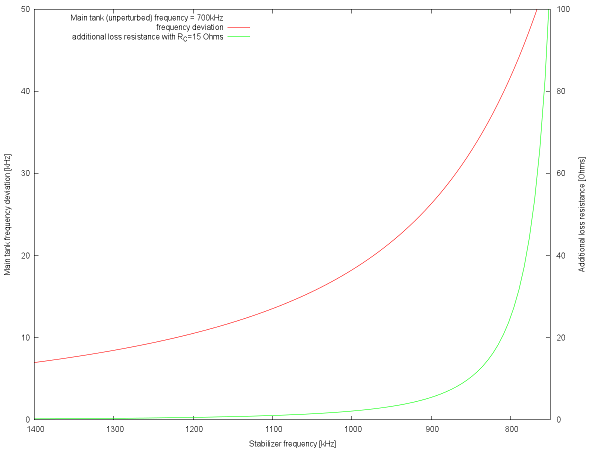 The red curve shows the detuning effect of the stabilizer circuit (left hand side Y-axis). From this graph one reads a detuning of approximately 50 kHz when the resonance frequency of the stabilizer tank approaches the (unpertubed) resonance frequency of 700 kHz of the main tank.
The green curve (right hand side Y-axis) shows how much additional resistive loss is exerted in the main tank, when an ohmic resistance of Rc = 15 Ω of the stabilizer coil "C" is assumed. One can clearly see how dramatically the main tank circuit losses increase as the stabilizer tuning approaches the main tank resonance frequency. So one understands, that without significantly detuning the main tank circuit, the stabilizer can be used to drain more or less energy from the main tank circuit and in doing so stabilize the operation of the Cockaday audion.
Increasing the resistance of the stabilizer coil "C"
The logical continuation of these investigations was to find an aswer to the following question:
What happens if the resistance of the stabilizer coil is further increased? To answer this question, two more LT-Spice simulations were run using Rc = 50 Ω (blue curve) and Rc = 100 Ω (brown curve):
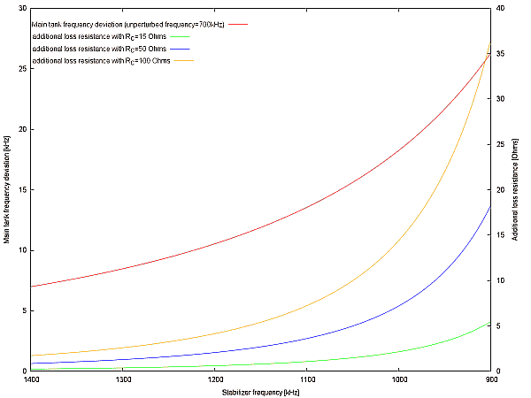 The red and the green curve are identical to the previous graph.
As one might expect, an increasing damping influence on the main tank circuit is observed in the case of higher Rc values (lower Q) of the stabilizer coil, while the detuning effect remains unchanged.
For higher values of Rc the resonance frequency of the stabilizer circuit needs not be tuned so exactly to the optimum found for lower values of Rc, which makes it easier to set the Cockaday audion to an optimum.
Measuring Q-Factors
Looking at these results, it remains a secret whether Cockaday himself knew this effect. In his descripiton he wrote that all coils were wound with the same copper wire. Only if a measurement of the Q-factors of the main tank circuit and the stabilizer circuit of an original Cockaday receiver were available, it could be decided whether Cockaday had this information. A lower Q factor of the stabilizer coil could have been realized even when using the same copper wire throughout, by inserting a layer of resistive material underneath the "C" coil.

This label was found inside the "D" coil of the only existing original Cockaday set that came to our knowledge.

This shows the interior of this original Cockaday set. The label can be seen inside the "D" coil. The markings "B1", "B2", "C1", "C2" denote the connections to the stabilizer circuit and the main tank circuit, respectively.
Regrettably we did so far not succeed in motivating the owner of this set to execute the Q measurements, i.e. the measurements that would give a final clue on whether Cockaday really used the same copper wire and coil body throughout or whether he used a special trick to make the "C" coil more lossy... but didn't tell anybody.
Fortunately, a Swiss Collector was more cooperative and made measurements of the Q-factors of his set, representing a much more precise copy of the Cockaday receiver than our setup. However, this is obviousely not an original Cockaday coil set, as can be seen by the different colour of the coil body, and the missing "Cockaday label".

Measurement of the main tank Q-factor Measurement of the stabilizer Q-factor
The Q-factor measurement was performed in the following way:
- Inject the generator signal using a small coil of few turns.
- Turn the condenser of the measured circuit to max. capacity.
- Short the other circuit (Done with the red wire jumper.)
- Tune the generator until the voltage across the measured circuit reaches a maximum. The voltage measurement is done using an oscilloscope with a 10:1 probe. By doing so, only the probe input capacitance of a few picofarad is added to the circuit capacity. Note this resonance frequency fres.
- Adjust the generator frequency to both sides of fres until the amplitude of the RF voltage drops to 70% of its max. value. Note both of these frequencies flower and fupper.
- Bandwidth of the circuit ist B = fupper - flower.
- Q-factor of the circuit then is Q = fres/B.
The measured values were:
- Main tank circuit ("B" / "F"): fresB = 482 kHz, B = 6 kHz, QB = 80
- Stabilzer circuit ("C" / "E"): fresC = 777 kHz, B = 16 kHz, QC = 48
The measurements revealed that the stabilizer circuit had a lower Q-factor than the main tank circuit. However, the ratio of QB / QC = 80/48 = 1.666... is (nearly) the same as the ratio of the resonance frequencies fresC / fresB = 777/482 = 1.612. Therefore the increased loss of the stabilizer coil "C" is due to the skin effect, and no additional damping is used.

This graph shows the skin effect for round wires with their diameter as a parameter. The light red area corresponds to the diameter of wires used in Cockaday tuner coils.
From the graph one reads a direct proportionality from frequency to increase of resistance.
The frequency of the RF voltage in all coils of the Cockaday tuner is determined by the received signal, therefore, if in the example above, the received frequency is 482 kHz, then the frequency of the voltage in the stabilizer coil also will be 482 kHz, and not the resonance frequency 777 kHz. That means the losses in the stabilizer coil will be lower, corresponding to the ratio of these frequencies. Therefore, less additional resistance is transformed into the main tank.
Measurements on our Cockaday tuner also show the same proportionality between frequency and resistance of the stabilizer coil. Indeed, we deliberately did not use a damping layer beneath the stabilizer coil.
For demonstrating the effect of increased loss, an additional ohmic resistor will be inserted into the stabilizer circuit.
Experimental results with increased resistance Rc
LT-Spice simulations as well as measurements on our setup showed that an increased resistance of the stabilizer coil "C" simplifies the tuning of the Cockaday audion.
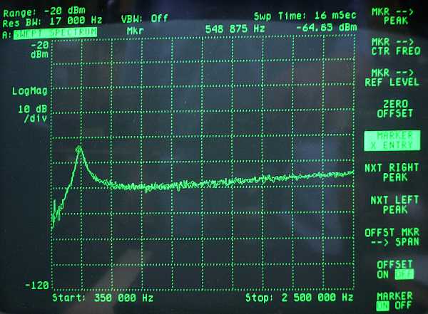
The following two pictures show the sweep response of the main tank circuit when the stabilizer circuit was made more lossy by inserting a variable resistor between "C" and "E". The stabilizer frequency remained (nearly) unchanged, and correspondes to the case (ii) "Coil "D" in wrong position" above. ["Main tank resonance frequency 529.625 kHz. Stabilizer tuned to a frequency above main tank resonance."]

Rc = 200 Ω Rc = 500 Ω
With Rc = 200 Ω a small shift of the resonance frequency (548.875 kHz: marker) of the main circuit is still recognized, but the amplitude curve only has a small bent, and no longer a pronounced "kink".
With Rc = 500 Ω no further influence of the stabilizer can be seen.
Although the coil "D" position is not optimal, no difference to the case Rc = 15 Ω in the resonance curve of the main tank is recognized.
In the context of lossy stabilizer coils it is interesting to look into Cockaday's instructions for the operation of the "Improved 4-Circuit Tuner":
Cockaday gives an advice how to tune the stabilizer circuit. For his realization of the set he used two identical "vernier variable condensers" of 500 pF with 4 inch knob and vernier knob. The advice reads: "Set both dials to the same figure".

Reading Cockadays simple "cooking recipe" in the light of the results of our investigations it seems to be most likely, that he must have used a stabilizer coil with a low Q-factor. Had he used a low loss stabilizer coil with high Q-factor, the correct setting of the controls of his receiver would have been far too sensitive. Considering that he delivered his 4-coil-sets to amateurs who used it to build a receiver, these assemblies would have never had identical electrical properties. Correct tuning of these sets with a high-Q stabilizer would have been possible in principle, but extremely cumbersome.
To render his receiver more "user-friendly" he used a low-Q stabilizer, and as a consequence the tuning procedure was largely facilitated.
Allthough all this seemed to be a strong indication that Cockaday used a stabilizer coil with low Q-factor, he never mentioned this point in his publications. In conclusion we have the impression that the stabilizer coil "C" was not made more lossy to facilitate tuning, but that really all coils were wound using the same wire. Tuning must have been tedious but possible after acquiring a certain degree of expertise with operating this set.
Demodulation quality
The demodulation measurements were performed with minimum Rc. The generator was set to a carrier frequency of 600 kHz with 30% AM modulation. The source resistance was set to 400 Ω, the RF amplitude was approx. 8 mV.
1. Demodulation test:
"B" voltage of the UX200 set below the ionization threshold of Ar-gas.
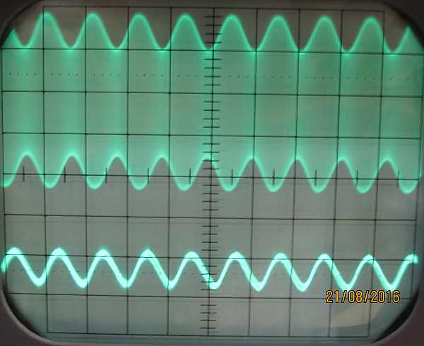

- On the left hand side, a picture of the AM modulated RF and (below) the demodulated AF is seen.
- The resonance curve on the right hand side, shows the main tank sweep response when the Cockaday tuner is properly aligned to get a clean demodulated signal.
2. Demodulation test:
"B" voltage raised to a level close to the ionization threshold of Ar-gas.This operation point is critical to reproduce.
Top: AM modulated RF signal,
bottom: the demodulated AF - already slightly distorted.
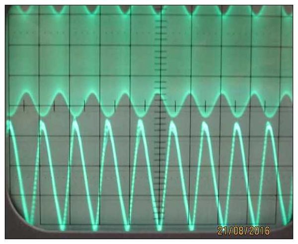
3. Demodulation test:

"B" voltage is just above the ionization threshold of Ar-gas.
Top: AM modulated RF signal, bottom: the demodulated AF - strongly distorted.
The demodulated signal still can be heard, but additionally a growling sound comes up. Raising the "B" voltage further produces very much noise, and the modulation signal is no longer heard.
Synchronous demodulation
When the Cockaday audion is properly adjusted (stabilizer resonance and "B" voltage), the demodulated signal has a small amplitude and very low distortion. This is an indication of synchronous demodulation.
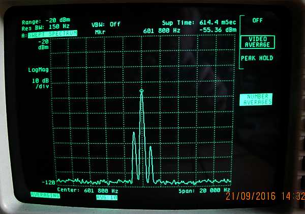
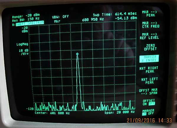
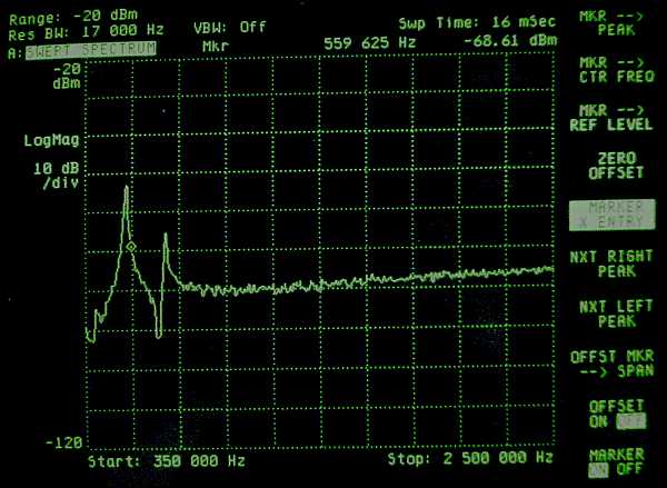
- On the left hand side the spectrum of the AM signal was measured at the plate of the UX200 when the signal was properly demodulated ("B" voltage below ionization voltage).
- On the right hand side the spectrum at the plate of the UX200 is shown, when the AM generator is removed from the Cockaday set after it was optimally tuned. This clearly shows that the Cockaday receiver uses synchronous demodulation.
Cockaday states:
"Of course, the receiver does not re-radiate; this is really important in these days when closely coupled regenerative receivers are the rule, and we have so much whistling and squeaking accompanying reception in a locality where a number of these re-radiating receivers are in use."
Although this statement is only partly true, it is not in contradiction with the synchronous demodulation capability of the Cockaday receiver.
- A synchronous demodulator indeed re-radiates. But the carrier it produces is faint and it is 100% synchronous to the carrier of the received station. This (locally) increased carrier reduces the modulation degree, and so the demodulated signal becomes lower. This effect is explained in "Regenerative Circuits with Real-Time Feedback Limiting".
- A re-radiated synchronous carrier reduces the modulation degree also in nearby receivers. But this is not recognized as a distortion.
- A nearby detector receiver will be able to hear a faint station, because the re-radiated carrier then produces an AM signal with a value above the detector's threshold. Such cases were reported, and this effect is called "Carrier Boost".
- "Normal" regenerative receivers are not synchronized to the carrier, and so produce whistles and squeakings.
- Synchronous reception could probably not be measured at those times.
B.t.w.: It was also possible to operate a Siemens 22Rfe TRF receiver in synchronous demodulation by raising the reaction. This resulted in a lower demodulated signal level, but with more fidelity, which is typical for synchronous reception. Joe Sousa also made this experiment on his visit to Berlin this summer.
Simplifying the setup
At some later point of our studies, the setup has been "simplified". The variable condensers "G" and "H" were replaced by fixed condeners, and the same was done for the variable rheostat "I". The corresponding values of these were found by measuring the variable items when the set operated well. Also the "X" potentiometer has been removed. As a replacement, a variable voltage divider for the "B" plate voltage of the UX200 audion valve was devised. So this plate voltage can be set from approximately 15 V to 23 V, a range that provided sufficient liberty of operation (see characteristics of the UX200 above.)

Re-checking the demodulation showed the significance of the value of plate voltage. It was set to 19,46 V to get an optimal demodulated signal. For lower plate voltages, the amplitude of the demodulated signal becomes lower, while for increased plate voltages no usable demodulated signal is obtained, due to the non-linear characteristics of the UX200.


Left hand side: stabilizer circuit is optimally tuned. Right hand side: stabilizer is slightly tuned to a lower resonance frequency: the amplitude of the demodulated signal "jumps".
When the stabilizer circuit is further detuned to lower or higher resonance frequencies, the Cockaday audion looses its synchronisation, and start whisteling.
Re-checking orthogonality of our coil arrangement
Initially, the orthogonal position of coil "D" was found before the wiring of the set had been completed. To confirm this point, the orthogonality of coil "D" had been re-checked.


Left hand side: resonance curve of main tank when stabilizer is "optimally" tuned to get the demodulated signals of the "simplified" set obove. Indeed, a small "kink" shows up at 1.79 MHz, when a 600 kHz signal is demodulated.
Right hand side: checking the orthogonality of coil "D" by tunig the stabilizer circuit to its lowest value 807 kHz. (Tuning of main tank remained unchanged.) A rather pronounced "kink" shows up at 807 kHz.
- These results demonstrate a loss of coil "D" orthogonality, due to the wiring of the set.
- Nevertheless, also in this "non-orthogonal position" of coil "D" a synchroneous demodulation is possible.
To re-establish the orthogonality, coil "D" had to be moved about 1 cm towards the center of coil "B".
In this position, the measured resonance curves no longer have a pronounced "kink".


Left hand side: stabilizer resonance at 1.79 MHz; Right hand side: stabilizer resonance at 807 kHz.
Now we expected the quality of the demodulated signal to be improved, and the tuning of the Cockaday set to be easier?


Left: plate voltage 18.21 V; Middle: plate voltage 18.36 V; Right: plate voltage 19.08 V
When coil "D" is in orthogonal position, a variation of plate voltage no longer results in a jump of the amplitude of the demodulated signal but in a continuous increase of its amplitude. However, between the two states, the demodulated signal becomes distorted.
Tuning the Cockaday audion with coil "D" in orthogonal position was not easier than in the "nearly orthogonal" position before.
Summary
In an attempt to clarify the mystery of the much discussed Cockaday receiver, we carried out a series of practical and theoretical investigations. For the practical investigations we built an as-close-as-possible replica of a Cockaday receiver using original documentation as a guide line. In particular the famous 4-coil set was constructed in accordance with Cockaday's prescriptions. Fortunately we could get hold of a gassy Ar-filled triode of the type originally used in Cockaday's sets (UX-200) - an essential "ingredient" of the receiver.
The Cockaday audion is a variation of the Deforest "Ultraudion", and its regeneration is controlled by increasing losses in the main tank. While a "normal" regenerative receiver is controlled by increasing the regeneration to a point close to oscillations, a Cockaday audion is controlled by increasing the main tank losses to a point where it performs "soft" oscillations, and so performs synchronous demodulation.
Our analysis of the "Cockaday Precision Coil" set revealed that the perpendicular coil "D", the exact position of which is not stated by Cockaday, is not in orthogonal orientation, and therefore couples to the other coils. However, in combination with the 1-turn antenna coupling coil "A" a bridge configuration is established, by which the influence of the stabilizer circuit "C" / "E" on the resonance curve of the main tank "B" / "F" can be compensated. As a consequence, the only influence of the stabilizer circuit on the main tank is an increase of its losses, and a (small) shift of its resonance frequency. This is reflected in the experimental results and can be theoretically demonstrated using LT-Spice simulation calculations on the basis of the "Cockaday Equations" (not yet published).
The measurements on our Cockaday replica showed that a slight deviation from the orthogonal position of coil "D" had no mayor influence on the quality of the demodulated signal.
Theoretical investigations showed that the tuning procedure of the Cockaday receiver can be facilitated by "artificially" increasing the losses in the stabilizer circuit, since by doing so, a stronger damping influence can exerted on the main circuit. But to our knowledge, and juging from available documentation Cockady did not render the stabilizer circuit intentionally more "lossy". So using this receiver, in particular setting the correct point of operation must have been rather tedious!
The operational behaviour of the Cockaday audion was strongly influenced by the gassy audion tubes used in those times. The plate voltage of the gassy tubes is extremely critical and has to be controlled within a fraction of a volt. The reason for this critical behaviour lies in the ionization voltage of the filling gas, which is 15.74 V for Ar gas. Using plate voltages above this critical level, electrons on their way from the cathode to the anode start ionising the filling gas. With increasing voltage, this ionisation starts progressively closer to the cathode. Since the Ar-ions move slower than the electrons (mass-inertia!), a positive space charge is built up, leading to signal response distortion and loss of regeneration control.
An essential feature of these tubes is their extremely low transconductance of less than 100 µmhos (0,1mA/V). Only such tubes can be used in direct feedback circuits like e.g. Cockaday and DeForest Ultraudion, since modern tubes with their much higher transconductance could not be stopped oscillating.
In retrospect it is difficult to judge whether Cockadays claim of his receiver being superior to other audions of the time was justified. But at least we managed to arrive at a better understanding of its operation and the complex role of its components.
Acknowledgement
The author wants to thank our "Cockaday team" for valuable contributions. Hans Knoll gave many practical hints since times, when the Cockaday set still was mysterious (see Cockaday Audion). Joe Sousa not only furnished the original tubes, but also valuable measurements on a Cockaday set, and LT Spice results. Jochen Bauer was the co-autor of the appended paper, and derived valuable formulae. Last not least Harald Giese was a great help in proof reading and finding a good English formulation of this post. To all of them, I am very grateful.
The whole "Cockaday team" also wants to thank Joerg Sigg for his Q-factor measurements.
To thank the Author because you find the post helpful or well done.