Wireless Radio Phonograph
Wireless Radio Phonograph

Not only since more and more German and European AM transmitters are switched off there are some alternative small homebrew transmitters in discussion and in use to keep the beloved AM radios alive.
For german articles on topic you can feed the [ SEARCH ] with "Heimsender" to get many interesting articles.
As examples in english: A simple one-tube transmitter is described in this article, and the Granco modulator there.
The circuit of a German factory-made "Heimsender" from year ~1928, the "Sendator", is attached in this article.
Here we are with a project issued earlier by "Popular Science Monthly" and later in the book "Radio For The Millions", extracted from page 112 -114 of the 3rd print of 1946:
"Wireless" Radio Phonograph
Requires no connection to the set
 Inexpensive and easy to build, this "wireless" record player may be used with any alternating-current radio receiver without making any actual connections to the receiver circuit. In addition, when you plug in a microphone and flip a switch, the
record player becomes a public-address system that will allow you to do your own program announcing through the radio's
loudspeaker. In use, the device is simply plugged into a convenient electric outlet.
Essentially, the "wireless" feature of the pick-up consists of a tiny radio transmitter (oscillator) tuned to a frequency around 550 kilocycles, or to any unused band at the upper end of your radio's tuning dial. The power of the little transmitter is, of course, very low, and the distance it may be placed from your receiver depends upon the radio's sensitivity. With a good superheterodyne, the phonograph can be used in an adjacent room. With less powerful receivers, it may be necessary to wrap the insulated antenna of the phonograph-transmitter loosely around the receiver's antenna lead-in, without making an electrical contact.
 |
|
Study the wiring diagram carefully. The set is actually a two-tube transmitter. Parts are best arranged as in the photo above. |
If the reader already has a synchronous electric turntable, and either a magnetic or crystal pick-up, he may use these with the wireless oscillator and avoid the expense of buying new ones. The oscillator circuit is built on a compact aluminum chassis measuring 1¼" by 2½" by 6½". A black crackle panel serves as the mounting for the trimmer condenser that adjusts the tiny 550 kilocycle radiofrequency transformer, the microphone jack, and the switch for changing from pick-up to microphone.
The two tubes used are a 25Z5, as a rectifier, and a 6A7, as a combined modulator and oscillator. Two 6,000-ohm, one-watt resistors, and two 16-mfd. electrolytic condensers are used for filtering the rectified current from the 25Z5.

Plugged into an outlet anywhere in the room with your radio, the unit "broadcasts" records through the loudspeaker.
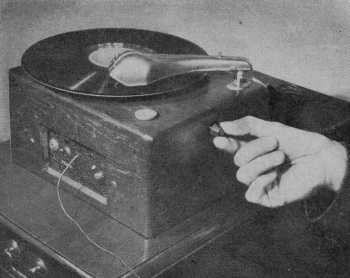
Volume is controlled by a knob mounted near the pick-up arm. The antenna, seen leading out of the cabinet, is stretched on the floor during Operation

By flipping a switch and plugging in the microphone, you've got your own public-address system for entertaining friends. How the synchronous motor for the turntable is installed may be seen at the left.
To obtain the best results with the carbon-type microphone recommended, a suitable transformer with a 200-ohm primary is used in conjunction with a 4½ volt "C" battery. As shown, the battery fits snugly inside the cabinet.
Care must be taken to follow the exact values of the fixed condensers and resistors specified in the wiring diagram, and under no circumstances ground any of the wiring to the chassis or panel. This is to prevent any possibility of shock should the user accidentally touch the chassis of the receiver while holding the pickup. Standard A.C.-D.C. antenna wire can be used for the aerial of the transmitter, which may be approximately twenty-five feet long. When making the wooden cabinet shown below, be sure and cut a ventilator opening in the back.
 |
| Details of the inexpensive wooden cabinet. No bottom is needed, but rubber feet should be used. |
LIST OF PARTS NEEDED
Rectifier tube, 25Z5.
Oscillator-modulator tube, 6A7.
Synchronous motor (2" deep).
Magnetic or crystal pick-up.
Radio-frequency transformer, 560 Kc.
(special).
Microphone transformer (midget).
Hand microphone (carbon-type).
Toggle switch.
Midget wafer socket, six-prong.
Midget wafer socket, seven-prong.
Two electrolytic condensers, 16 mfd.,
175 volt.
Two tubular condensers, .05 mfd.
Tubular condenser, .1 mfd.
Trimmer condenser, 350 mmfd.
Mica condenser, .00001 mfd.
Mica condenser, .00004 mfd.
Mica condenser, .002 mfd.
Two resistors, 6,000 ohm, 1 watt.
Resistor, 1,500 ohm, 1 watt.
Resistor, 10,000 ohm, ½ watt.
Line-cord resistor, 290 ohm.
Volume control and switch, 500,000 ohm.
Miscellaneous: — Aluminum chassis, crackle panel, microphone jack and plug, A.C.-D.C. antenna, cabinet, etc.
Exceptionally above wiring diagram is shrinked - you can enlarge it to full-size.
If you have no turntable with synchronous motor available I think it doesn't matter: Today a cheap MP3 player wil store the program for a complete radio-day.
A source for elder American radio programs is "transmitted" on the website of Mr. Bix Eiben in Hamburg (Germany): www bixeibenhamburg.com
Best Regards,
GR
To thank the Author because you find the post helpful or well done.