granco: Granco-AM Modulator/transmitter.
granco: Granco-AM Modulator/transmitter.

Fellow radiophiles,
The Granco ARC60 FM converter for the car has a built-in AM modulator circuit that could be used as a home AM transmitter. One advantage of this circuit is it's low 12.6V operation. Otherwise, converter tubes such as the 12BE6 have been popular tubes for use in home am transmitters. (use 6BY6 or similar with sharp cutoff, as described by Jacob in the next post. 2009-10-22)

C25 is the last FM detector filter, and passes audio into the modulator through the bandpass filter comprised by R14, C26, C27, R17. The audio modulation input for the tube is the first suppressor grid at pin 7. This grid has a remote cutoff characteristic because it is normally used for AGC when this tube is used as an AM converter at the front end of an AM car radio.
R15 may be grounded or tied to 12.6V via a 390k resistor that is not present in this schematic. Use whichever configuration makes the oscillator work reliably. This is probably what was done at the factory.
L8 is a common local oscillator coil that is found in most radios.
L9 is a 1mH RF choke, and could be replaced with a tuned loop for effective magnetic radiation of the signal.
The data sheet for the 12AD6 has these conversion transconductance values for three bias levels at G3:
G3=0V > Gc=260uS
G3=-1.8V > Gc=20uS
G3=-2.2V > Gc=5uS
These values and the grid leak bias of -0.8V suggest that the audio modulation input should not be much above 1Vp-p.
A low impedance earphone output of a CD player driving pin 7 directly may give good results.
Don't expect low distortion modulation much beyond 50%.
One clear advantage of this type of home am transmitter is that the local oscillator runs at a fixed amplitude, and it is it's output that is modulated by G3. This reduces, or eliminates, oscillator regrowth distortion when the modulation is too deep with a plate modulated oscillator.
Another useful characteristic of this oscillator is that the separation between the tank circuit and the output reduces the effect that the antenna has on frequency.
If your AM radios have a wire antenna, then a wire antenna should be tied to the antenna output of this circuit.
If your AM radios have a loop antenna, or ferrite stick antenna, then you should use a tunned loop in place of L9. This tuned loop could be a ferrite stick, or a home made loop. If you don't tune the loop. the reach of the transmission will be reduced.
In my case, I simply drive an external tuned ferrite stick antenna, without any modifications to the Granco. This setup has a range of about 3 feet. The existing 10k plate resistor widens the bandwidth of the loop by at least a factor of 10.
For more examples of AM transmitters check the list that is included in 1.5V AM tube transmitter.
Regards,
-Joe
To thank the Author because you find the post helpful or well done.
Heptode AM modulators

Hello Joe and fellow radio enthusiasts,
from one point of view this Granco ARC60 AM modulator is an interesting circuit.
But I have some serious doubts, whether this modulator circuit may meet more than very modest requirements.
To achieve a modulation degree of more then a few %, a tube with AGC characteristics may not be used.
However, using heptodes with sharp-cutoff characteristics will allow modulation degrees up to 100 %.
Single-heptodes as the 6BY6; 1680; 2032; 5915 = EH900S = EH960; E91H = 6687; and some further equivalents of them will give good results at screen voltages of 75 to 85 volts and plate voltages of 75 to 250 volts. I never tested them on lower voltages as shown in the circuit above.
The European triode-heptodes ECH84, ECH200 and PCH200 are also well qualified. Their triode section may be used as audio preamp or oscillator.
The next issue of this Granco modulator is its local oscillator which is operated between grid 1 and cathode of the modulator tube, in the same way as in a normal receiver front end, using pentagrid converter tubes like 6SA7 or 6BE6.
Some years ago I've made an experimental setup, operating a 6BY6 or 1680 this way.
By increasing the (amplitude) modulation as usual, a considerable degree of frequency modulation occurred. At higher modulation levels the frequency modulation grew such as high as to make it impossible to tune-in the signal on a normal bandwidth AM receiver without severe distortion !
As a consequence, a heptode modulator requires an external oscillator to obtain a constant frequency.
If properly designed, Heptode modulators are very well suited as very-low-power transmitters for home-service purposes.
To achieve close-to-broadcast quality one should pay attention to some requirements:
-
a heptode with sharp-cutoff characteristics on both grid 1 and grid 3;
-
an external oscillator to generate the carrier frequency,
-
the carrier frequency signal should be fed to the heptode grid 1, while
-
the audio signal should be fed to grid 3;
-
the audio input at grid 3 must be kept free from any RF signals, strayed-in by the oscillator circuit or by the plate output.
further recommendations:
-
a buffer stage between oscillator and heptode grid 1;
-
a PLL or X-tal controlled oscillator;
-
a low-impedance driver stage (e.g. cathode follower) at grid 3 audio input, combined with a RF/HF suppressor.
Best Regards, Jacob
To thank the Author because you find the post helpful or well done.
More than meets the eye/ear
Hello Jacob and fellow radiophiles,
Thank you very much for bringing your experience to this topic. I have read your excellent German language posts on this topic with Google-Tranlate, and they were part of the reason why I posted the Granco modulator. I will list them here for reference:
http://www.radiomuseum.org/forum/modulator_fuer_lang_und_mittelwelle.html#post114490
http://www.radiomuseum.org/forum/schaltschemas_fuer_modulator.html
My original post was based on my casual listening appraisal of my ARC60 Granco FM converter, as working well. Now I need to make some measurements just to see what it takes to make the modulator go sour.
I am going to take advantage of your advice on pentagrid modulators to look for particular trouble with the Granco modulator.
Two of the things I will look for are FM shift and modulation depth.
----------------
On FM shift, the pentagrid modulator grid sequence with G3 steering current between G2 and G4, is designed to reduce the effect of the AGC control voltage applied to G3, but there are limits to this isolation, and you found trouble with this, so I will look for it.
A moderate variation in oscillator amplitude may be tolerable because the the LO is only providing class C cathode current pulses.
The FM variation as a result of the audio input is more troublesome. This makes me suspect of an oscillator circuit that was overdriven. The wave at the oscilator coil should look distortion-free at the negative peaks, when the cathode is conducting. This means that the timing of the oscillator is determined nearly exclusively by L and C, and not by the hard driven widened negative peak from the cathode. The low capacity gimmick wire feedback at pin3 of L8, and the high 330k grid leak resistor R15 and the low L8 tap drive by the cathode, suggest that this is a lightly driven oscillator.
Many pentagrid converters work with grid leak resistors in the 20k-30k range, and they ofthen drive relatively high tap in the coil. Do you remember seeing a clean sinewave on the LO coil you worked with?
The lightly driven mode of oscillation is generally desirable because is gives good supply rejection and immunity from emission decay over the life of the tube. I found this to be the case with the LO of my Grundig 80u (post 5) .
One symptom of an overdriven local oscillator, is a slow-down of frequency with higher supply voltages.
I will report back on what I find relating to undesired FM, by sweeping a DC voltage at G3.
----------------
On modulation depth, it seems that the cut-off of G3 is not all that remote. The low voltage at G2=11.5V makes it possible to reduce plate current from 220uA with G3=0V to 20uA with G3= -2V. The G3 control curve also looks farly smooth/linear in this range. Perhpas the low G2 screen voltage operation puts the 12AD6 in a different class, as compared to the high voltage pentagrid mixers.
The following plot from the 12AD6 General Electric data sheet, is for the external LO excitation, as you recommend, to avoid disturbing the oscillator with modulation. I will have to see if I get results anywhere near this nice, with the self-excited Granco modulator.
I have a related question: How much modulation is reasonable to aim for in a home modulator?
I understand modulation and sound as a dB world. Aiming for 50% modulation, with the occasional peak exceeding it, seems reasonable to me, if the dynamic range of the sound material has already been professinally mixed/compressed to be very predictable, as would be the case with FM broadcasts, or CD music. I know that early 1920's detectors often give less distortion with modulation under 50%-peak.
Perhaps our resident Sound Engineer, Herr Bernhard Nagel, could give some advice on modulation depth.
Regards,
-Joe
To thank the Author because you find the post helpful or well done.
12AD6 AM modulator response
Hello again Jacob,
As promised, I made a DC sweep of the third grid G3 and recorded the frequency and output RF amplitude.
Your suspicions about frequency drift and amplitude linearity were confirmed to a point, despite the useability of the modulator.
Under normal operation, the RF output modulation reaches 50% on the highest peaks. A trapezoidal modulation display, with RF in the Y axis and live FM audio in the X axis, showed pretty good linearity, easily better than 10%, for the worst deviations.
Please note that the RF output plot on the right was taken with a 10x probe, so the vertical axis should be multiplied by 10. Click the plots to enlarge.
Summarizing these results, a negative bias of -0.7V, with 1.4V p-p audio input would yield 80% modulation at low amplitude distortion from 50mVrms to 250mVrms.
But there is a price in unwanted FM, which, for this range, is 5kHz. This is probably the maximum that could be tolerated. If the modulation is kept below 50%, as is the normal operating range for the ARC60, then the FM deviation is only 3kHz.
The RF output was loaded with a parallel tuned Ferrite stick. The Ferite loop Q with the internal R16=10k plate load should be quite low, and not have a significant effect on spurious AM modulation from the FM shift. I use this Ferrite stick to couple to an AM radio within 3 feet.
FM deviation will cause the most distortion in radios with narrow band IF. Radios with a wide band IFsetting should be relatively immune to FM distortion.
The power supply voltage was 13.8V, which is nominal for a car battery.
The sinewave at the top of the LO tank circuit looked very clean, without any signs of overdrive, and the total amplitude variation at the tank circuit with a G3 variation from 0V to -2.5V was under 30%.
I was very surprised to see this much FM shift. It makes me wonder how AM radios with pentagrid converters stay aligned for strong and weak signals, over wide AGC variations.
This also makes a case for the European Hexode-Triode converter valve.
This also makes me appreciate the dificulties in designing a good pentagrid converter tube and a good pentagrid converter circuit.
Your suggestion to use a separate oscillator should be quite adequate to eliminate oscillator drift. It is hard to see the need for more than that. After all, nearly all superhet AM radios are stable enough to not need retuning of the LO.
Regards,
-Joe
To thank the Author because you find the post helpful or well done.
Crest of unprocessed audio signals

The crest factor of unprocessed audio signals easily is in the order of 10 to 12dB. Unprocessed means not processed by an audio compressor like OPTIMOD®. In vintage AM times only the reduction of the dynamic by sound engineers was usual which did not reduce the crest factor.
10dB is approximately a factor of 3 in voltage. So if no overmodulation must occur, only an average (or effective) modulation degree of 30% then was allowed. And vintage transmitters did not afford more.
For a home constructed AM modulator this values still hold also today.
Regards,
Dietmar
To thank the Author because you find the post helpful or well done.
Neutralization
Thank you for the crest factor clarification. I will remember 10dB as a rule-of-thumb for crest factor.
Beyond automated compression, the type of music may also affect crest factor. For example, popular music is usually mixed to have as narrow a dynamic range as possible, while classical music usually has the widest dynamic range from the softest to the loudest instruments and from solos to full orchestral blasts.
WGBH is a local FM station in the Boston Massachusetts area, with a lot of classical music content. They were reputed to modulate less than what the FCC (Federal Communications Commission) wanted, because they wanted to leave room for the soaring blasts of symphonic music.
On the other hand, WBUR is an FM station with many talk programs, and they usually turn off the multiplex modulator during voice transmissions.
After some reflection about the possible cause of the FM shift of the modulator, one factor that could be investigated is the possibility of Miller feedback capacitance that is highest when the modulation is at peak envelope.
The shape and direction of the curves in the plots above are consistent with this suspicion. The frequency is lowest when the output is highest.
Jacob's warning about keeping G3 free from RF, speaks to the problem of Miller capacitance feedback.
Miller feedback is not a factor in a mixer application because the LO voltage at the plate is shorted out by the IF filter load, and the oscillator amplitude is pretty well isolated from AGC control.
Perhaps a proper neutralization of the Miller capacitance would eliminate the FM deviation.
Regards,
-Joe
To thank the Author because you find the post helpful or well done.
Stabilized
I felt strongly about the possibility of Miller capacitance feedback from the plate circuit to the control grid circuit as a possible explanation for the FM effect, so I set about to see if I could eliminate the FM deviation by shorting out the plate load resistor R16=10k.

This updated frequency plot shows the original RED trace with the undesirable FM deviation that accompanies the desired AM modulation at G3.
The BLUE trace was measured with the plate load resistor R16=10k shorted out, and shows the frequency as measured with a 10x 12pF probe at the cathode of the 12AD6 pin 2. This low impedance point was chosen because it is not strongly affected by the 12pF load of the probe.
Shorting out the 3VRMS plate swing at the plate has a strong effect on FM deviation. In fact, it appears that there is an similar, but opposite feedback capacitance from a node that is inverted with respect to the plate voltage
My intention was to neutralize the Miller feedback capacitance using conventional neutralization methods, but when I realized that there was what seems like an existing feedback path of the opposite polarity, I decided to adjust the plate swing until the FM deviation was eliminated.
The BLACK trace shows the final Stabilized version of the circuit, with a 24 Ohm resistor as the plate load R16. This load resistor reduced the plate swing from 3V rms to 400mVrms.
The reason why the cathode traces are not completely above the red trace in the frequency plot, is the slight 12pF capacitive loading of the scope probe at the cathode.
One fundamental aspect of Miller feedback capacitance is that it depends on a voltage gain and on a passive capacitance. The Miller-multipled capacitance is the product of the gain times the passive capacitance. This multiplcation effect is the reason why a small capacitance, such as 0.1pF has a large effect after being multipled by gain.
When modulation is applied at G3, the gain between the control grid G1 and the plate is purposely changed. This is the gain factor in the aforementioned Miller capacitance. This explains how the Miller-multiplied capacitance depends on AM modulation.
This Miller capacitance multiplication effect is often used in a "reactance" tube to apply AFC to the local oscillator of an FM receiver. The Reactance tube has it's output capacitively coupled to the LO, and takes DC input from the FM detector.
Very strangely, Miller Capacitance should be neutralized to improve frequency stability in Oscillator designs where Miller capacitance is one of the factors determining the total resonant capacitance. Once the Miller capacitance is neutralized, the only effect that tube voltage gain has is to change the oscillation amplitude.
An inspection of the circuit layout shows that some of the stray capacitive coupling from plate to control grid G1 is due to poor layout. The wiring at the plate is withing 0.5 inches (1cm). The two yellow arrows show the plate wiring next to the oscillator coil.

The following plot shows that the plate loading has no effect on the Amplitude modulation.

I write this post while listening to a local classical music station on the Granco ARC60. My Nordmende Transita picks up the signal from the Ferrite loop stick plugged into the Granco output. The sound is very nice. I have a scope probe on the audio input to G3, and the p-p swing never exceeds 0.5V. This small swing, along with the elimination of spurious FM deviation on the AM output from the Granco, explain the nice sound.
Prof. Rudolph shared some comments in a private email and brought up the very low distortion modulator he built around a resistor stabilized oscillator conceived by Terman.
This oscillator is interesting in that the oscillator tube is run over a portion of it's power-law transfer characteristic, so that the plate current is always on over the oscillating cycle, and is much more linear than the pulsed current of the oscillator in pentagrid converter.
The resistance coupling from the plate to tank circuit helps filter the distortion that must be present at the plate, and the sinewave at the LC tank has very little distortion.
Some distortion at the plate current is absolutely necessary for amplitude stabilization, but this distortion is effectively filtered by the R feeding the LC tank. If the RLC tank has a Q on the order of 100, which is generally not hard to achieve, any distortion present at the plate, which is likely to be mostly second harmonic, will be reduced by at least 40dB, at the tank circuit.
Another point that Prof Rudolph brought up was the challenge of finding a clear channel for use with a home modulator/transmitter.
I have found that sometimes, what appears to be a clear channel, because there is no audible speech, actually still has enough carrier present from a distant station, that will become immediatelly audible as a whistle. So now, I usally look for a clear channel with my modulator on, but with audio off and look for a spot that has no whistles. Finding a clear channel is good for me and for my neighbors.
Lastly, Prof Rudolph, acknowledged the useful information he got from Jacob Roschy that he used in his modulator design. And I must now acknowledge the vital contribution that Jacob made to this thread. If it were not for Jacob's contributiion, I would not have missed an insteresting lesson in oscillator frequency deviation/drift.
Best regards,
-Joe
To thank the Author because you find the post helpful or well done.
My AM modulator career
Hello Joe and all fellow radio enthusiasts,
I started experimentations using multiple grid tubes as AM modulators already in my youth, as described in post #16 in this thread, first I used the octode AK2, soon followed by the RENS1234 (E449).
As I realised that a considerable audio distortion was caused by the AGC characteristics of these tubes, I looked about a tube with sharp-cutoff characteristics on both control grids and found the 6BY6.
The audio quality by using the 6BY6 was much better than before, but still was not fully satisfying. Speech transmission was OK, but music appeared to be increasingly blurred, the more tones were played simultaneously.
This caused me in the mid of the 1990s to do a lot of investigations in order to improve the sound quality of my heptode AM modulator. I tried negative feedback without success.
By one of these attempts I used a penthode as audio driver instead of a triode as before, with the result of a noticeable increasing of this blurring effect !
Very soon I realised this can only be caused by the higher internal resistance of the penthode compared to the triode. The conclusion was, using a driver with low impedance will solve the problem !
By scoping the signal at grid 3 I also observed a small amount of RF voltage, strayed-in from the oscillator circuit. I concluded this RF voltage on the wrong place may cause undesired mixing products that causes this blurring effect !
Since then, it became standard for me, to drive the audio input to grid 3 with low-impedance, performed by a cathode follower driver, combined with a RF/HF suppressor.
During these investigations in the mid 90s, I also made this experimental setup, operating the 6BY6 with this cathode-coupled oscillator, as told before.
Since it resulted in this heavy frequency modulation, I abandoned this experiment and scrapped this circuit very soon, I will never use this any more !
As far as I can remember, I used an original oscillator coil from a (radio) pentagrid converter circuit, as well as the usual 20...22k grid leak resistor.
As you (Joe) figured out, this frequency modulation may be caused by the possibility of Miller capacitance feedback, makes it clear, this circuit will never be suitable as AM modulator.
The reason why this circuit performs well as frequency converter in a receiver, is only because the oscillator frequency is suppressed at the plate of the tube.
Best Regards Jacob
To thank the Author because you find the post helpful or well done.
Some Miller feedback due to wiring.
Hello Jacob and fellow radiophiles,
I read your post again. Sometimes there are things I don't get completely with Google-Translate.
I mentioned parasitic capacitance between wires as a possible path for the unwanted Miller feedback that causes the FM deviation.
I was able to eliminate all FM deviation simply by reducing the plate swing, so I felt no need to shield the L0 from the plate. However, for designs that have a separate LC oscillator in the form of a triode-hexode, or even a completely separate LC oscillator triode, the effect of wire coupling can cause unwanted frequency shifts due to Miller capacitance modulation.
The following is an updated Frequency plot showing improved FM deviation in the Magenta trace after I added a grounded copper foil shield around the oscillator coil, the grid and cathode pins of the 12AD6.
Shielding the wiring is clearly not enough to eliminate all Miller feedback, but it ilustrates how careless lead dress adds over 2kHz of frequency shift between the original Red trace and the Magenta trace with the shielded oscillator coil.
The actual frequency of the Magenta trace was 7.7kHz higher at -2.5V G3 bias due to the copper shield, but I shifted it down in the plot to coincide with the left end of the Red trace for easier comparison.
I recomment owners of Triode-Hexode transmitters to check their FM deviation because of the obvious proximity of oscillator and modulator.
As a last measurement of the Miller feedback capacitance from the plate to the control grid G1, I injected a 10Vp-p square wave at the plate at 3MHz and measured 40mVp-p at the control grid, which is also pin3 of L8. My scope probe has about 67pF in the 1x setting, plus a few more pF from the circuit, would give around 75pF at the control grid. This yields a Cga, grid-to-anode capacitance, of 0.3pF. This is indeed, a pretty high Cga. A good IF pentode may have one tenth of that capacitance.
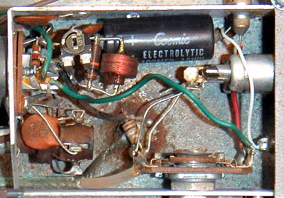
The first photo shows the original AM modulator section of the ARC60, and the second photo shows the temporary copper shield over the AM oscillator section. A trimpot is visible near the R16=10k resistor and plate load coil L9. The trim pot was disconnected for the shielded measurements. The brown-black-white banded beige component is the 1pF capacitor to couple the modulator output. Note how it is wired so close to the oscillator coil at the lower left.

spurious FM deviation check
One method to check FM deviation of your current home AM transmitter would be to drive the audio input with a sub-sonic frequency, like 10Hz, and tune your transmitter to a frequency that is very close to the frequency of another source. This frequency could be a broacast station, a lab frequency generator, or simply the leakage from the local oscillator of lightly shielded superhet radio.
The idea is to listen for Vibrato in the beat tone as the two trasmissions are received, while ignoring the Tremolo effect of the amplitude modulation.
You can also simply drive your modulation input with DC and listen for the beat frequency shift as you vary the DC input over the audio modulation range.
Going Further
I looked up the characteristics of the 6BY6 heptode by GE. The early part of the G3 control of plate current looks indeed very linear, then it gets rapidly non-linear near cut-off. For example, the top plate curve shows a plate current variation from 7.5mA with G3=0V to 0.7mA with G3=-11V So it should be possible to get 90% modulation with little distortion. This is consistent with the very good results that Jacob got with his 6BY6 modulator. The majority of the music material uses the center third of this curve, as Prof Rudolph explains with the Crest Factor of music material, so the distortion in this zone should be very low, indeed.
I have far too many other projects to play with currently, and hopefully share them here in the forum. Besides my intent with this thread was to share, then later study the Granco modulator. It would be interesting to see if someone can come up with a neutralized self-oscillating 6BY6 modulator design.
I learned an enormous amount about neutralization in this forum ( how many Hans Knoll posts has everyone read showing yet another form of neutralization, or another unwanted coupling path in need of some neutralization? - Thank you Hans!).
Very few American radios after the 20's used any explicit neutralization, but it remained fairly common in European radios to get the last bit of performance.
Most of the existing Heptode modulator designs have a coil load at the plate, so it would not be too hard to get a tapped coil that offers the necessary inversion from the plate voltage, to couple via a small capacitance to the control grid, until all FM deviation is eliminated.
Another common Neutralization technique in European radios, is the capacitive divider from the plate circuit to the screen grid. Andreas Steimetz posted an excellent German Language article on this topic. I read it with Google-Translate.
Regards,
-Joe
To thank the Author because you find the post helpful or well done.
G3 Remote cutoff limitation, neutralization.
The following plot shows the limitation that the remote cut-off characteristic of G3 in 12BE6 pentatgrid places on the maximum undistorted modulation depth.
The Ib curve shows a very linear relation to Grid-Number 3 (G3) for values of G3 between -4.5V and 0V. The plate current Ib in this range modulates from 3.4mA with G3=0V to 1.1mA with G3=-4.5V. This is a 2.3/3.4*100=68% maximum linear modulation. Below -4.5V soft limiting starts with the remote cut-off characteristic at G3.
![]()
If you can tolerate the -3dB received audio loss from reducing peak modulation to 67%, you should get very linear reception, if you also did the proper Miller compensation to avoid spurious FM deviation.
If you exceed 67% peak modulation, you should hear the sour intermodulation distortion that Jacob found unacceptable. I think I would find it unacceptable too.
If your music material is symphonic music, you will venture so infrequently into high modulation peaks, with the high crest factor of symphonic music, that occasionally exceeding the 67% knee may be tolerable. But if your music material is more like chamber music, or popular music. Then the overmodulation will be a frequent irritant if you set your modulation more than the -10dB-3dB=-13dB from the peak RF output. The -10dB is the crest factor described above by Prof Rudolph, and the -3dB is the 67% modulation knee.
(I think that that hard rock or "heavy metal" music has the smallest dynamic range I have ever heard. Typically, there is a heavily limited/distorted electric guitar drone at a very steady level. The irony is that this type of music is "loud" at any listening level. Rock musicians were pretty clever when they started to apply spread-spectrum techniques with heavily distorted cords to fill the sound space along the frequency axis. Simply adding watts to understorted cords does not give the same sensation of loudness that can't be turned down.)
I added the 12BE6 plot to help me understand the distortion that Jacob heard when he was using the this type of tube. Now this thread has three examples of G3 characteristics that are good (6BY6), fair (12AD6) and undesirable (12BE6).
One thing to keep in mind if considering a Miller compensation method that uses the screen grid (G2+G4) with the 6BY6 is that the plots in this thread show that the screen current is higher than the plate current by about a factor 2.This is a very different relation than for a conventional IF pentode, like the EF89, where the screen current may be just one third of the plate current.
Comments invited.
Regards,
-Joe
To thank the Author because you find the post helpful or well done.
The development of my AM modulators
Hello Joe and all fellow radio enthusiasts,
following I show the development of my AM modulators with multiple grid tubes.

The octode attempt
As my first attempt I used the octode AK2.
The oscillator circuit works in the same way as in a normal receiver circuit using the AK2 as frequency converter. The AF signal is applied to control grid g4, grid bias is obtained from cathode trimpot P21.
Since g4 has AGC characteristics, no optimum operating point could be found.
At low negative grid bias the carrier signal was big, the modulation was relatively clear and undistorted, though only faint.
By increasing the neg bias, the carrier signal decreased, while the modulation became louder, but even increasingly distorted.
This would have been quite useful for speech, but for the more desirable transmission of music it sounded rather evil than nice.
So I could only find the best possible compromise, which was never fully satisfying.

The hexode attempt
This caused me to look for better solutions.
So I changed the octode AK2 against the hexode RENS1234. Since it didn't have a separate oscillator unit, an additional triode REN904 was required as oscillator tube.
The sound quality was definitely better as with the AK2. This was caused by the lower AGC characteristics of a single grid of the RENS1234, but it was still too much distorted.
The RENS1234 has strong AGC characteristics only if AGC voltage is applied to both control grids g1 + g3.
To thank the Author because you find the post helpful or well done.
The sharp-cutoff heptode solution
As I realised that the audio distortion was caused by the AGC characteristics of these tubes, I looked about a multiple-grid tube with sharp-cutoff characteristics on both control grids and found then the 6BY6.
Quality management
The audio quality by using the 6BY6 was much better than before, but still was not fully satisfying. Speech transmission was OK, but music appeared to be increasingly blurred, the more tones were played simultaneously.
This prompted me in the mid of the 1990s to do a lot of investigations in order to improve the sound quality of my heptode AM modulator. I tried negative feedback without success. By one of these attempts I used a penthode as audio driver instead of a triode as before, with the result of a noticeable increasing of this blurring effect !
Very soon I realised this can only be caused by the higher internal resistance of the penthode compared to the triode. The conclusion was, using a driver with low impedance will solve the problem !
By scoping the signal at grid 3 I also observed a small amount of RF voltage, strayed-in from the oscillator circuit or even from the plate. I concluded this RF voltage on the wrong place may cause undesired mixing products that causes this blurring effect !
Since then, it became a standard application to me, to drive the audio input to grid 3 with low-impedance, performed by a cathode follower driver, combined with a RF/HF suppressor.

The circuit shown in Fig. 12 is the result of these investigations.
V2 is the sharp-cutoff heptode 6BY6 or a similar type, as modulator tube. V1 is one section of a 12AU7 / ECC82 as oscillator triode. The tuned circuit L11 and CV11 (+ C13) defines the carrier frequency.
V3 is the other section of the 12AU7, acting as low-impedance cathode follower AF driver to g3 of the 6BY6. Capacitor C23 suppresses RF in the g3 circuit, there are also C46 and C32 to keep the AF line clean from RF dirt. V4 is the AF preamp, in this case a 6AK5 in triode connection.
Operating B+ voltage is about stabilized 200 volts, while the heptode screen grids g2 + g4 are operated at 85 volts, stabilized by a 85A2 / 0G3.
As I realised, most datasheets suggesting 75 V as screen voltage for sharp-cutoff heptodes such as 5915, 6687, E91H and EH900S, I will also prefer 75 V as screen voltage in future projects, probably stabilized by a 75C1 or a 0A3.

The cathode oscillator attempt
During these investigations in the mid 90s, I also made this experimental setup as shown in Fig 19, operating the 6BY6 with this cathode-coupled oscillator, as told before.
Since this resulted simultaneously with the desired amplitude modulation into a strong undesired frequency modulation, I abandoned this experiment and scrapped this circuit very soon, I will never try this any more !
As far as I can remember, I used an original oscillator coil from a (radio) pentagrid converter circuit, as well as the usual 20...22k grid leak resistor.
As this frequency modulation may be caused by the possibility of Miller capacitance feedback, clearly proofs this circuit as never be suitable as AM modulator.
The reason why this circuit performs well as frequency converter in a receiver, is only because the oscillator frequency is suppressed at the plate of the tube.

The triode-heptode solution
Back to normal:
The use of the sharp-cutoff triode-heptode ECH84, which is easy to obtain in Europe, facilitates the AM modulator circuit and limits the tube number to 2.
The amplification factor of the ECH84 triode section has µ = 50, which makes it best suited as AF preamp V4.
The ECH84 heptode section V2 works in the same way as the 6BY6 shown in Fig. 12, as well as both sections of the 12AU7 / ECC82 working as oscillator triode V1 and AF driver V3.
Attachments:
- MDL12-6BY6_en (11 KB)
- MDL12-6BY6_en_ctd-osc (10 KB)
- MDL11-ECH84_en (13 KB)
To thank the Author because you find the post helpful or well done.