- Land
- Grossbritannien (UK)
- Hersteller / Marke
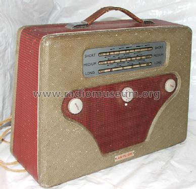
- Amplion (Brand), Alfred Graham & Co., Graham Amplion Ltd., Amplion (1932) Ltd.; London
- Jahr
- 1952 ?
- Kategorie
- Rundfunkempfänger (Radio - oder Tuner nach WW2)
- Radiomuseum.org ID
- 112018


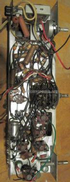
I remade the power source by AC100V.


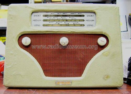
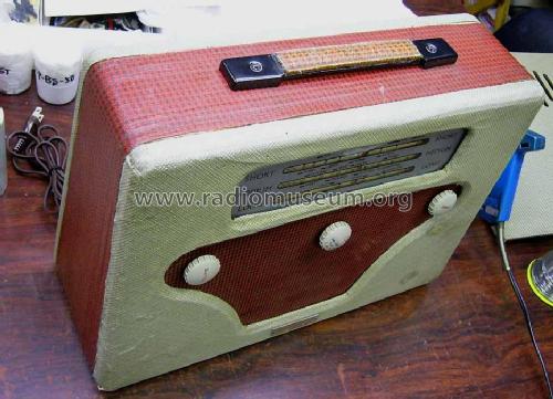
Bad woodworm! Otherwise original.

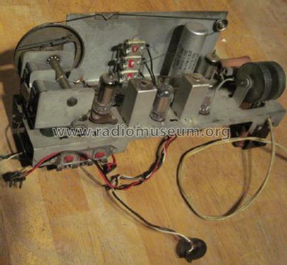
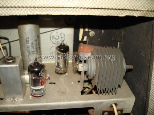
DL94 at top DK92 at bottom of photo.
Klicken Sie auf den Schaltplanausschnitt, um diesen kostenlos als Dokument anzufordern.
- Anzahl Röhren
- 4
- Anzahl Transistoren
- Halbleiter
- Metal-rectifier
- Hauptprinzip
- Superhet allgemein; ZF/IF 470 kHz; 2 NF-Stufe(n); kein Zusatz
- Anzahl Kreise
- 6 Kreis(e) AM
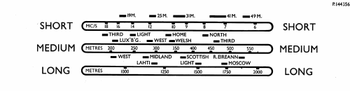
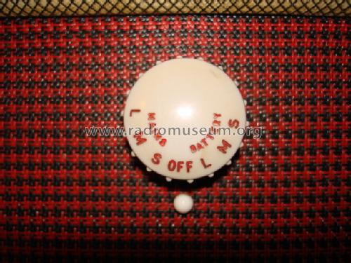
- Wellenbereiche
- Langwelle, Mittelwelle und Kurzwelle.
- Betriebsart / Volt
- Netz- / Batteriespeisung / 195-215; 215-235; 235-255 / 90 & 7.5 Volt
- Lautsprecher
- Dynamischer (permanent) Ovallautsprecher / Ø 9 cm = 3.5 inch
- Belastbarkeit / Leistung
- 0.25 W (max./spitze)
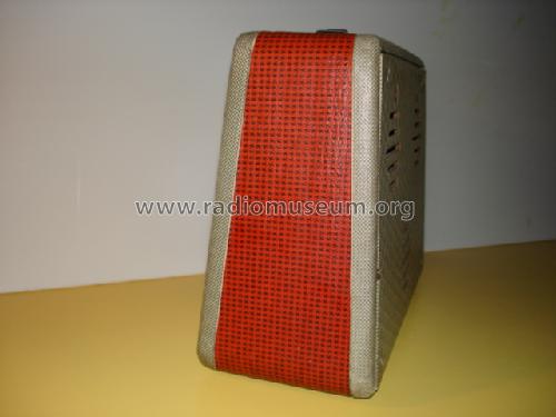
- Material
- Leder / Stoff / Plastic / Segeltuch über div. Material
- von Radiomuseum.org
- Modell: Alternative - Amplion Brand, Alfred Graham &
- Form
- Reisegerät > 20 cm (netzunabhängig betreibbar)
- Abmessungen (BHT)
- 380 x 270 x 160 mm / 15 x 10.6 x 6.3 inch
- Bemerkung
-
The valve & battery guide label only instructs the owner to communicate the serial number, no model is mentioned. Loudspeaker about 4" x 6". Case is Rexine style cloth over plywood.
Batteries either
HT Ever Ready B126 / Vidor L5512 with LT Ever Ready AD38 / Vidor L5048or longer life
HT Ever Ready B138 / Vidor L5536 with LT Ever Ready AD43 / Vidor L5060A "7.5V" set is actually nominal 6.8V. Sentercell Selenium Metal Rectifier for HT/LT from mains (direct).
Warning: Chassis may be live when connected to AC or DC mains.
Price of 17 "Guineas" (£17, 17s) included purchase tax but excluded batteries.
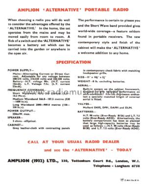
Weight excluding batteries listed as 8lb in brochure.When choosing a radio you will do well
to consider the advantages offered by the
'ALTERNATIVE.'
LT current 53mA.
External aerial option fitted for "short wave enthusiast"
- Nettogewicht
- 3.5 kg / 7 lb 11.3 oz (7.709 lb)
- Originalpreis
- 17.35 GPB
- Datenherkunft
- - - Data from my own collection
- Literaturnachweis
- - - Manufacturers Literature
- Autor
- Modellseite von Taizo Nagahiro angelegt. Siehe bei "Änderungsvorschlag" für weitere Mitarbeit.
- Weitere Modelle
-
Hier finden Sie 100 Modelle, davon 80 mit Bildern und 9 mit Schaltbildern.
Alle gelisteten Radios usw. von Amplion (Brand), Alfred Graham & Co., Graham Amplion Ltd., Amplion (1932) Ltd.; London
Sammlungen
Das Modell Alternative befindet sich in den Sammlungen folgender Mitglieder.
Forumsbeiträge zum Modell: Amplion Brand,: Alternative
Threads: 1 | Posts: 2
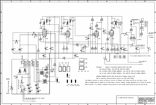
I have uploaded a reverse engineered schematic based on my model. I may have made mistakes.
Issues:
The HT to LT dropper is unmarked and the 1.96 K Ohms seems unlikely high. The value in other sets with nominal 50mA series (closer to 54mA) is 1.7K to 1.85k. 1.96K would imply 105HT. The other resistors in dropper measure as marked and with a 1N4007 instead of the two SenTerCel rectifiers HT is close to 90V. Putting 15K in parallel brings LT to 6.7V (ideal is 6.75, absolute maximum is 7) with 228V AC and tap at 215 .. 235V.
The compensation for the DL94 HT current flowing into the filament circuit is definitely not enough. Adding the two extra 1K resistors marked R101 & R102 fixes this. Normally I like to leave stuff orginal, but this is likely something that might have had a service bulletin. My model is only S/N 1182, perhaps later models where changed?
The mains on/off/battery switching isn't safe! The chassis can be live. The CenTerCell, Droppers and main HT capacitor are "live" even with switch at Off or Battery!
The HT- series resistor for HT current saving on Battery is only 82 Ohms. Typical sets with Series filaments and DL94 are 220 Ohm to 330 Ohm. This (like other makes) is shorted out on Mains operation.
Alignment:
There are marks on the rear scale. These have been approximately matched with printed scales to get alignment point numbers. The set can be mostly aligned out of the case with patch cords to the two loop aerials. One loop shared for MW/LW is many turns and the other loop is one or two turns probably. These are in grooves on the outside of the cabinet, taped over and just under the Rexine. The two close togther contacts are the MW/LW loop. The SW signal connects to contact under handle and then from side of case to the series "loading" coil is mounted between chassis and a spare tag on the LW loading coil. There is an unused capacitor to adjoing tag, no doubt for an external SW aerial.
The IF frequency appears to be 470kHz, with each IFT can having two cores, one is under chassis (typical double tuned IFT as per my schematic). Use a loop on the signal generator and loosely couple with radio loop. IF can be checked by tuning radio to 550m as there is no IF trap.
The drive cord is simple, but doesn't seem well engineered. Move the cord drum as close to scale plate and not flush with end of shaft or the cord will fall off edge of drum.
Power
Because it's 1/2 Wave and perhaps nearly 65mA total mains current, use on a Shaver Transformer is marginal even though they are rated at 20VA (the consumption should be about 15W). I have Shaver Transformers in boxes with an extra hole drilled for UK earth pin of a 5A 3 pin plug to stop the old sets with risky isolation being plugged into a simple UK to 2 pin adaptor. These also work 110V AC sets up to about 15W. I add a 2n2F 1kV class X & Y ceramic capacitor to a pin common to 110 & 220V outlets to mains earth or else there is a lot of mains noise. Otherwise the earth only connects to panel and transformer core, not to any of the 5A plug pins.
Michael Watterson, 05.May.14