Sachsenklang M4
Böhm-Automatic, Glauchau (Ostd.) (D)
- Hersteller / Marke
- Böhm-Automatic, Glauchau (Ostd.) (D)
- Jahr
- 1970 ??
- Kategorie
- Ton-/Bildspeichergerät oder -Spieler
- Radiomuseum.org ID
- 166461

Sachsenklang Wandbox ca. 1972

Innenansicht ohne Verstärker

Münzbehälter Nachbau
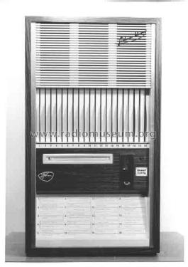
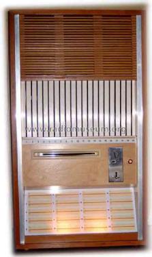
Original Herstellerfoto Frontansicht
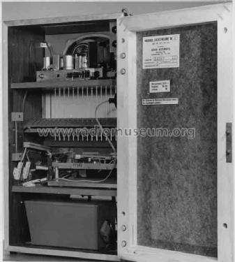
Original Herstellerfoto Innenansicht
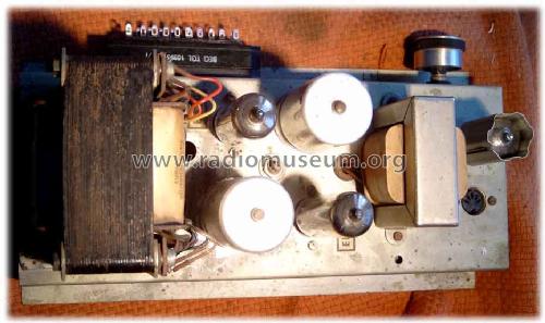
Originalverstärker von oben
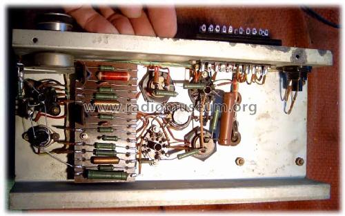
Originalverstärker von unten

Verstärkernachbau
Klicken Sie auf den Schaltplanausschnitt, um diesen kostenlos als Dokument anzufordern.
- Anzahl Röhren
- 3
- Hauptprinzip
- NF-Verstärkung
- Wellenbereiche
- - ohne
- Spezialitäten
- Jukebox - Musikbox
- Betriebsart / Volt
- Wechselstromspeisung / 220 Volt
- Lautsprecher
- Dynamischer (permanent) Ovallautsprecher
- Belastbarkeit / Leistung
- 5 W (Qualität unbekannt)
- Material
- Gerät mit Holzgehäuse
- von Radiomuseum.org
- Modell: Sachsenklang M4 - Böhm-Automatic, Glauchau Ostd
- Form
- Diverse Formen, unter Bemerkung beschrieben.
- Abmessungen (BHT)
- 445 x 795 x 335 mm / 17.5 x 31.3 x 13.2 inch
- Bemerkung
- Letzte von Böhm-Automatic Glauchau gebaute Musikbox. Sogenannter Halbautomat bei dem die Platte (20 Stück zur Auswahl) von Hand in den Schlitz (Plattenschlucker) eingeschoben werden. Nach Einwurf von 2 x 10 Pfennig bekommt der Verstärker die Anodenspannung. Nach dem Abspielen wird diese wieder abgeschaltet, die Platte ausgeworfen und die beiden Münzen fallen in die Kassenbox. Gehäuse aus furnierten Spanplatten (17 mm stark). Anschlüsse für Fernregler und Zusatzlautsprecher. Eingebaut ist ein Ziphona A30 mit magnetischem System 4M. Wandbox, für Service nach vorn schwenkbar, aber auch als Standgerät zu benutzen.
- Nettogewicht
- 30 kg / 66 lb 1.3 oz (66.079 lb)
- Literaturnachweis
- Musikbox-Buch "Johann Strauß meets Elvis"
- Autor
- Modellseite von Uwe Ronneberger angelegt. Siehe bei "Änderungsvorschlag" für weitere Mitarbeit.
- Weitere Modelle
-
Hier finden Sie 4 Modelle, davon 4 mit Bildern und 3 mit Schaltbildern.
Alle gelisteten Radios usw. von Böhm-Automatic, Glauchau (Ostd.) (D)
Sammlungen
Das Modell Sachsenklang befindet sich in den Sammlungen folgender Mitglieder.
Forumsbeiträge zum Modell: Böhm-Automatic,: Sachsenklang M4
Threads: 1 | Posts: 1
Fellow radiophiles,
In a recent German language thread Uwe Ronneberger showed that the remote volume control of the Sachsenklang juke box is implemented as a variable resistor at the cathode of the input ecc83/12AX7 preamp. This is done because the low impedance of the cathode has a low sensitivity to stray electric fields of hum or other noises, and also because the high impedance of the input volume control would cause high frequency loss with the capacitance of a shielded cable.
In post 3 of the same thread, Jacob Roschy righly pointed out that this method of volume control can distort with high input drive signals. Jacob also points out the use of the EF83 remote cutoff pentode with a cutoff characteristic that would suit gain control of audio signals.
I was curious about what it takes for to overdrive the original implementation with the cathode resistor and a sharp cutoff triode. I expected that keeping the cathode unbypassed would improve the gain control action and prevent distortion, but I wanted to figure out just how effective this was.
There are two basic types of gain control that can be implemented at the cathode.
The only difference is that the cathode is no AC bypassed to ground in one case but it is bypassed in the other case.
The stage gain for U1 is determined by the value of the plate load R1=47k, the internal plate resistance, the cathode resistor U2=0-25k and the transconductance of the ECC83, gm<1.5mS depending on bias.
The stage gain for U5 is the same as for U1, except that the value of the cathode resistor U4=0-25k no longer affects the stage gain directly because it is bypassed by C3=10uF.
U4=0-25k only controls the stage bias, which affects gm, and ultimately also affects stage gain.
The second form of gain control with the bypassed cathode is equivalent to a grounded cathode where a negative DC bias is fed separately to the grid.
At full gain, with the pot set to zero Ohms, the two stages are equivalent, and they can both amplify a 1Vp-p signal with low distortion, perhaps around -40dB=1%, as LTspiceIV simulation suggests.
Plate cutoff occurs when the grid voltage multiplied by mu matches Bplus, or when Bplus/-mu=-2V. Under optimum conditions, the edge of cutoff will be reached with a 2Vp-p sinewave riding on a -1V grid bias.
I am ignoring for the sake of simplicity, the built-in -0.7V contact potential at the grid. This causes grid current to flow when the grid voltage rises above -0.7V with respect to the cathode.
The plot shows a sequence of seven simulations for various pot resistance values: 25K, 12.5K, 6.25K, 3.125K, 1.56K, 781R, 24R. The first in this series is shown in the black trace. The first plot shows DC curve tracings of the third tube just to demonsrate fairly reasonable modeling of the triode characteristic.

When the pot resistance is increased, the two stages respond very differently.
In the unbypassed-cathode stage, the gain drops as much at -30dB with the pot set to 25k and the distortion improves from -40dB to -60dB=0.1%, for the same 1Vp-p input.
in bypassed-cathode stage, the gain only drops around -6dB with the pot set to 25k, and the distortion worsens from -40dB to -10dB=30% for the same 1Vp-p input.
The trouble with the bypassed stage is that as the DC cathode bias was increases with a higher cathode resistor, the -2V cutoff point was reached because the cathode could not follow the input.
The unbypassed stage had no trouble with the increased cathode bias because the cathode was free to follow most of the input so that the net p-p AC signal between grid and cathode V(grid,Cathode) was reduced at higher bias levels, and the -2V cutoff point was never reached.
Compare V(grid,Cathode) which drops with pot resisance increase to V(grid,CathodeC) with stays constant.
(click the plots to enlarge)
 This plot shows the spectral content of the waves in the previous plot.
Note the improved distortion and gain control range for the unbypassed version, as compared to the bypassed version.
The same color sequence applies.
The dB scale is referred to 1Vrms.
Summarizing:
Max gain is 24dB=16, and distortion is -40dB=1% for both stages.
Min gain for the Unbypassed stage is -6dB=0.5 with -60dB=0.1% of distortion.
Min gain for the Bypassed stage is 17dB=7 with -10dB=31% of cutoff clipping distortion.
Conclusions
A sharp cutoff triode can be used for gain control with a variable cathode resistor, if the resistor is unbypassed so that it does most of the AC signal gain control by attenuation of the AC signal instead of relying on a reduction of gm from the bias change.
But either configuration will clip or cut-off input signals greater than 2Vp-p because they go below -2V at the grid. For larger signals, a three terminal voltage dividing potentiomenter would work best, as it has an attenuation range exceeding the -30dB seen in the unbypassed cathode case, and there is no distortion in the pot.
To a first order, the pot resistance of the unbypassed case could be made infinite for complete attenuation of signals less than 2Vp-p without clipping, but this makes the design of the pot difficult.
My choice of simulation values for the pot resistance in steps of 2 suggest that a log pot would work best for cathode gain control.
The grid-plate transfer curves of the EF83 remote cutoff pentode suggest that it could be used to increase the range of input voltages that could be controlled, if the screen voltage is run at the higher 200V rating for this tube. At lower screen voltages, soft distortion will become apparent for inputs that are several volts p-p.
But there is one fundamental advantage of the EF83 over sharp cutoff tubes, and that is that it's gain can be controlled electronically by changing it's grid bias voltage, while retaining a pretty good maximum input signal range at a given distortion. This tube would be ideal for AGC control in voice tape recorders.
The LTspiceIV simulations files are available via email: k2w at philbrickarchive dot org. LTspiceIV is a free spice simulator from www.linear.com
Comments invited,
-Joe
Joe Sousa, 23.Jan.10