- Pays
- Italy
- Fabricant / Marque
- Vega, BP Radio, Brionvega, Brion & Pajetta; Milano, Lissone (MI)
- Année
- 1964–1971
- Catégorie
- Récepteur de télévision ou moniteur
- Radiomuseum.org ID
- 172137


ebay.it #370912285684 seller robertom60
ebay.it #390655597176 seller michiviti

ebay.it #370912286321 seller robertom60
ebay.it #370912285684 seller robertom60
ebay.it #370912285684 seller robertom60

ebay.it #370912273595 seller robertom60
ebay.it #370912273595 seller robertom60
Ebay Auktion 180483622451
Ebay Auktion 180483622451
Ebay Auktion 180483622451

ebay.it #370912286321 seller robertom60


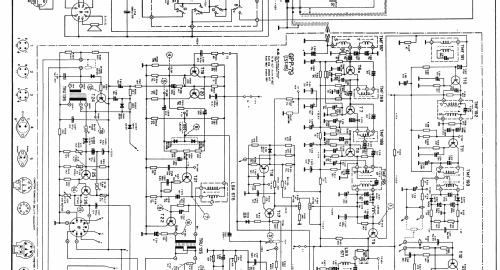
Cliquez sur la vignette du schéma pour le demander en tant que document gratuit.
- No. de tubes
- 2
- No. de transistors
- 29
- Semi-conducteurs
- AF139 AF109 BF163 BF159 AF126 BF160 AC141 AC138 AC142 BF178 or. BF174 BC281 or. BC178 or. BC262 or. BC252 BC107 or. BC171 or. BC280 or. BC176 BC301 or. BFY50 or. BC119 AU110 BC303 or. BFX88 or. IW9837 AC127 AD149
- Principe général
- Super hétérodyne (en général)
- Gammes d'ondes
- VHF/UHF (voir details en note)
- Tension / type courant
- Secteur et accus rechargeables (eventuellement piles) / AC 125; 160; 220 / DC 12 Volt
- Haut-parleur
- HP dynamique oval à aimant permanent
- Matière
- Plastique moderne (pas de bakélite, ni de catalin)
- De Radiomuseum.org
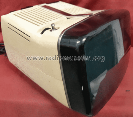
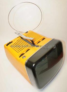
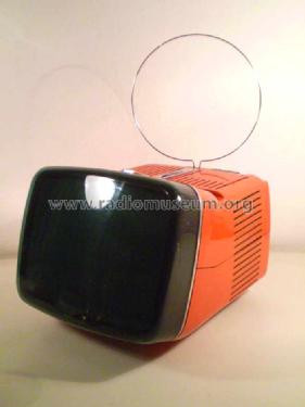
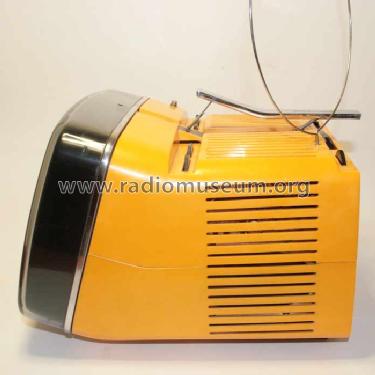
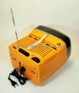
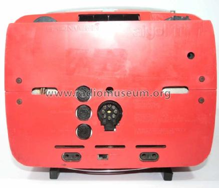
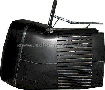
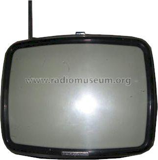
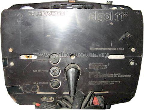
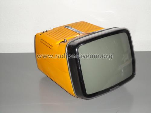
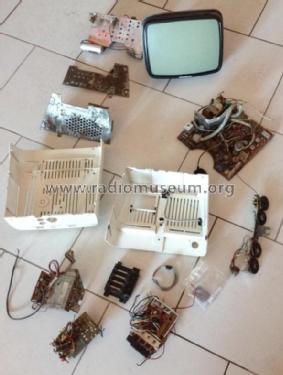
- Modèle: Algol 11" - Vega, BP Radio, Brionvega,
- Forme
- Modèle de table générique
- Dimensions (LHP)
- 270 x 220 x 310 mm / 10.6 x 8.7 x 12.2 inch
- Remarques
-
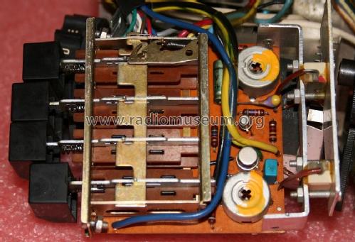
Brionvega algol 11" b/w TV. Design by Richard Sapper and Marco Zanuso. 4 program presets. Cabinets in different colors.
Transistors listed once per type. The EHT rectifier can either be a valve (DY51) or a semiconductor stack (TV11K) in later versions.
Notes:
- The schematic for "Serie U" mentions the picture tube as V2, but there is no V1. In earlier revisions position number V1 was most likely used to designate the DY51 EHT-rectifier. In "Serie U" a TV11.6K70 or a TV11K semiconductor stack is used as an EHT-rectifier instead.
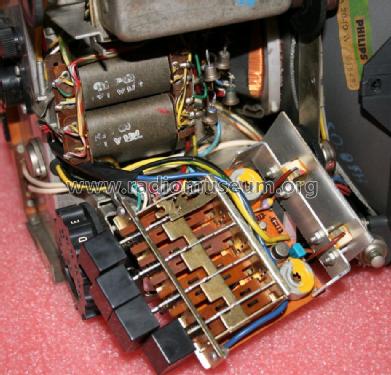
- "Serie U" sets were either fitted with a VHF tuner GRF119/B (channels E2 - E12) for Europe or with a VHF tuner GRF119/D (channels A - H) for Italy. The UHF tuner is a GRF515/B in both cases.
- Different revisions of this model are known.
See also later models Algol 2, Algol 3, Algol 4 , Algol 11" TVC with color, and the 2007 limited edition by Super//Fluo.
La versione "VR" (1973) dispone di tuner a Varicap e tastirera a quattro canali con 3 bande ( I , III , e IV/V ) selezionabili.
The 1973 "VR" version has a four channel keyboard for I, III and IV/V bands with a Varicap type tuner.
- Poids net
- 7.8 kg / 17 lb 2.9 oz (17.181 lb)
- Littérature
- -- Original-techn. papers. (Schematic Algol serie U)
- Schémathèque (2)
- Schemario tv ed. CELI n° 28 pag. 19
- Auteur
- Modèle crée par d'un membre de A. Voir les propositions de modification pour les contributeurs supplémentaires.
- D'autres Modèles
-
Vous pourrez trouver sous ce lien 232 modèles d'appareils, 133 avec des images et 118 avec des schémas.
Tous les appareils de Vega, BP Radio, Brionvega, Brion & Pajetta; Milano, Lissone (MI)
Collections
Le modèle Algol 11" fait partie des collections des membres suivants.
Contributions du forum pour ce modèle: Vega, BP Radio,: Algol 11"
Discussions: 1 | Publications: 1
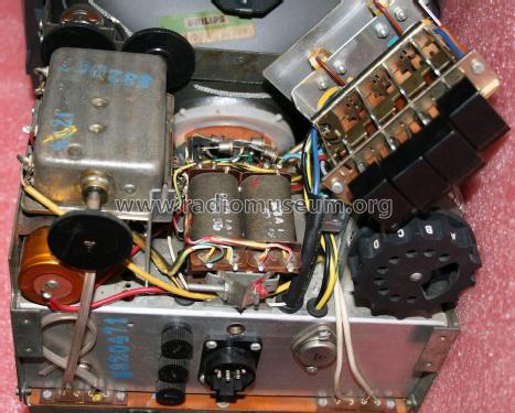
Breve descrizione del circuito di alimentazione (basetta GRP 75)

Pièces jointes
Tonino Giagnacovo, 31.Jan.13