- Pays
- Canada
- Fabricant / Marque
- Canadian Marconi Co. Ltd. (CMC, Esterline), Marconi's Wireless; Montreal, QC
- Année
- 1941 ?
- Catégorie
- Radio - ou tuner d'après la guerre 1939-45
- Radiomuseum.org ID
- 299007
-
- alternative name: CMC Canada || Marconi, Canada

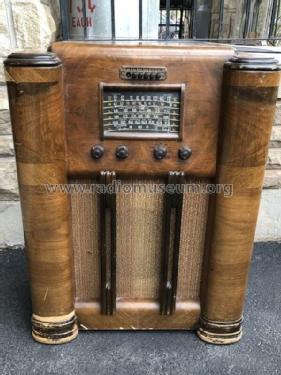
Cabinet of Marconi 207
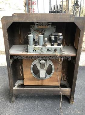
Back of Marconi 207

Dial of Marconi 207

Label for Marconi 207

Chassis of Marconi 207
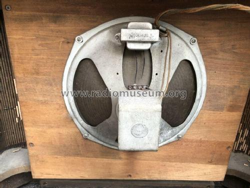
Speaker for Marconi 207
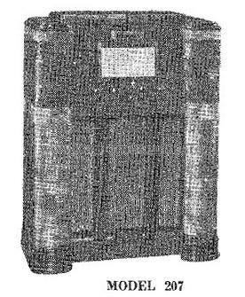
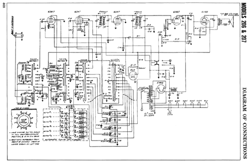
From service manual.
Cliquez sur la vignette du schéma pour le demander en tant que document gratuit.
- No. de tubes
- 7
- Principe général
- Super hétérodyne avec étage HF; FI/IF 462.5 kHz; 2 Etage(s) BF
- Circuits accordés
- 7 Circuits MA (AM)
- Gammes d'ondes
- PO et plus que 2 x OC
- Tension / type courant
- Alimentation Courant Alternatif (CA) / 115 Volt
- Haut-parleur
- HP dynamique à électro-aimant (électrodynamique) / Ø 12 inch = 30.5 cm
- Puissance de sortie
- 3.5 W (8.5 W max.)
- Matière
- Boitier en bois
- De Radiomuseum.org
- Modèle: 207 - Canadian Marconi Co. Ltd. CMC,
- Forme
- Console avec des boutons-poussoirs
- Remarques
-
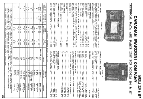
The Canadian Marconi model 206 is a 7-tube console radio with tuning eye tube and pushbutton station selector. Covers the following ranges:
Band Frequency (kHz) Standard Broadcast 540 - 1710 Shortwave 5860-16030 31m 9450 - 9750 25m 11645 - 11965 19m 15050 - 15400 Shortwave 17600 - 22040
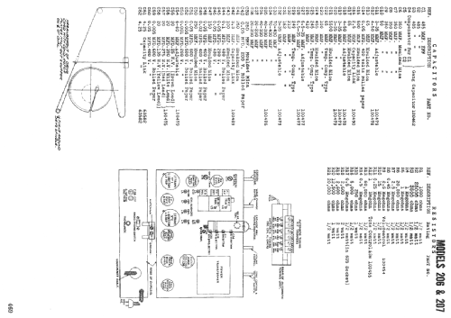
- Schémathèque (1)
- Marconi Service Manual (Volume 1) (P. 467-470)
- Auteur
- Modèle crée par Tom Seeger. Voir les propositions de modification pour les contributeurs supplémentaires.
- D'autres Modèles
-
Vous pourrez trouver sous ce lien 462 modèles d'appareils, 325 avec des images et 378 avec des schémas.
Tous les appareils de Canadian Marconi Co. Ltd. (CMC, Esterline), Marconi's Wireless; Montreal, QC
Contributions du forum pour ce modèle: Canadian Marconi Co.: 207
Discussions: 1 | Publications: 2
This is my first renovation, and my first post, so I'm a bit reticent in case I have my finding wrong. But I don't think so!
This is the Marocni 207, electrically identical, I believe, to the 206, and I'm looking at R18 / R19 in parallel, which feed voltage to the screen grids of the first & second stages of the RF path. The components list shows these as 2K6, 2W each, to give a combined value of 1K3 at 4W.
In my restoration of serial no. 4511, the parallel pair shows 40K instead of the advertised 1K3. That's a clue! But the resistors themselves have colour coding for 26K, not 2K6. Looking at the specs for these two valves (sorry, I can't get used to calling them "tubes," even though I now live in Canada), it's clear that a value of 1K3 for the resistor pair just doesn't work. 13K is better.
So I'm postulagting that the components list has the values wrong. Does that make sense? If I get agreement, I'll re-post this as information.
I'm finding that antique radio restoration is a combination of detective work, logic, and hard-earned knowledge. I love it!
Alistair Thomson, 25.Nov.18