T-195/GRC-19
Collins Radio Company; Cedar Rapids (IA)
- Country
- United States of America (USA)
- Manufacturer / Brand
- Collins Radio Company; Cedar Rapids (IA)
- Year
- 1952–1964
- Category
- Commercial Transmitter (TX not Transceiver)
- Radiomuseum.org ID
- 207003


21/11/11
21/11/11
21/11/11
21/11/11
21/11/11
21/11/11
21/11/11

21/11/11
21/11/11
23/11/11
1788R
Click on the schematic thumbnail to request the schematic as a free document.
- Number of Tubes
- 20
- Valves / Tubes
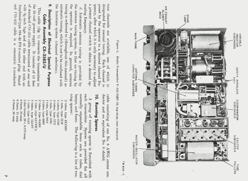
- 5726 5749 5749 5751 5751 5751 5763 5763 5814A 6AU6WA 6AK6 6AK6 6AQ5W 6AQ5W 6AQ5W 12AT7 12AT7 0A2 4X150D 4X150D 4X150D
- Number of Transistors
- Semiconductors present.
- Semiconductors
- Main principle
- Transmitter
- Wave bands
- Wave Bands given in the notes.
- Power type and voltage
- Storage Battery for all (e.g. for car radios and amateur radios) / 28.5 Volt
- Loudspeaker
- - - No sound reproduction output.
- Material
- Metal case
- from Radiomuseum.org
- Model: T-195/GRC-19 - Collins Radio Company; Cedar
- Shape
- Boatanchor (heavy military or commercial set >20 kg).
- Dimensions (WHD)
- 560 x 290 x 360 mm / 22 x 11.4 x 14.2 inch
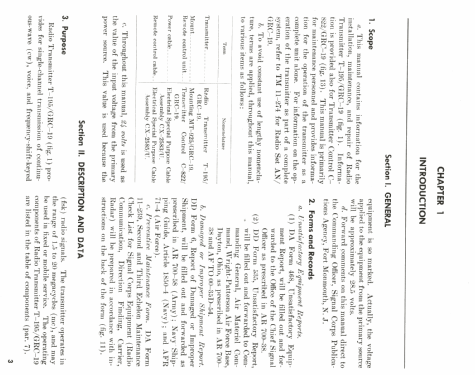
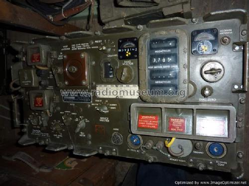
- Notes
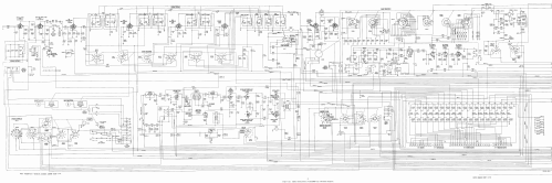
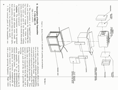
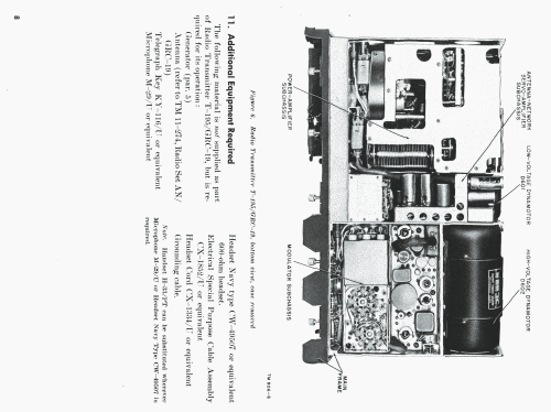
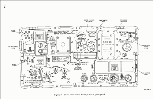
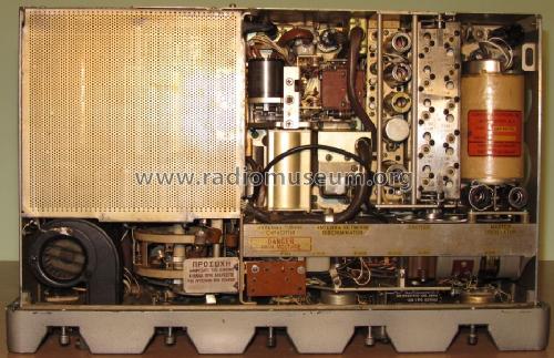
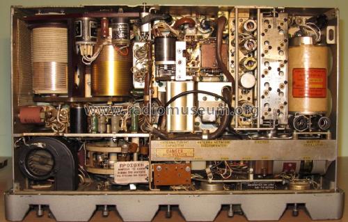
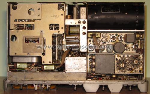
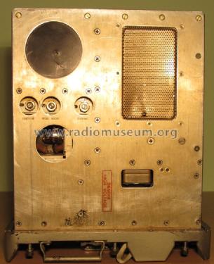
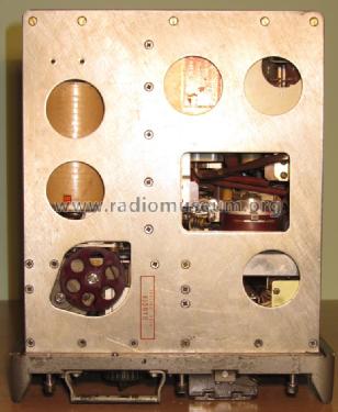
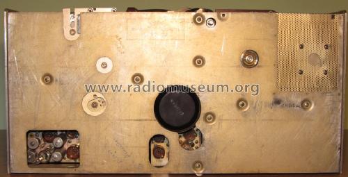
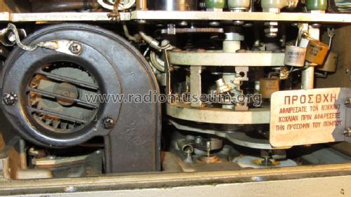
- Collins T-195/GRC-19 radio transmitter. Also made by other manufacturers.
Three variants: T-195/GRC-19, T-195A/GRC-19, T-195B/GRC-19.
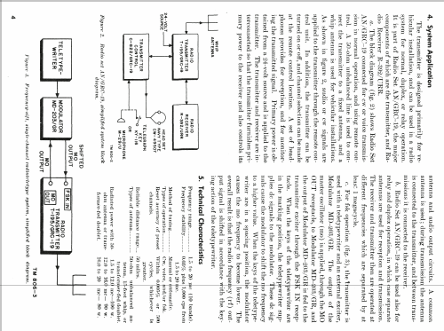
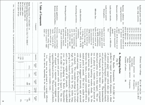
Coverage 1.5 to 20 MHz in 10 bands, CW/AM and FSK with a matching converter (MD-203/GR).
Power out (max): 100 W CW, 60 W AM.
Power in: 250 A startup (less for the A/B variants), 44 A operation, 9 A standby at 28.5 vdc.
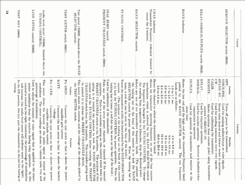
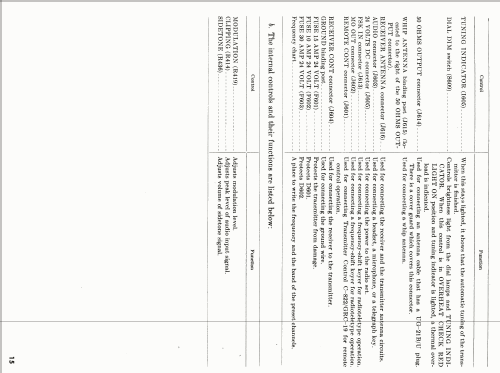
Frequency readout provided by 4 mechanical counters (4 digits each). 7 preset memory. Auto-tune system. 50 ohm or whip antenna connections. All connections on the front panel.
Used as a part of AN/GRC-19 vehicular system, matching receiver R-392/URR.
- Net weight (2.2 lb = 1 kg)
- 122 lb (122 lb 0 oz) / 55.388 kg
- Source of data
- - - Manufacturers Literature
- Author
- Model page created by Konstantinos Christoforou. See "Data change" for further contributors.
- Other Models
-
Here you find 103 models, 83 with images and 35 with schematics for wireless sets etc. In French: TSF for Télégraphie sans fil.
All listed radios etc. from Collins Radio Company; Cedar Rapids (IA)
Collections
The model T-195/GRC-19 is part of the collections of the following members.
Forum contributions about this model: Collins Radio: T-195/GRC-19
Threads: 1 | Posts: 1
Radio transmitters
T-195/GRC-19, T-195A/GRC-19, T-195B/GRC-19
Tube layout
|
Reference symbol |
Function |
Type T-195/GRC-19 |
Type T-195A/GRC-19 T-195B/GRC-19 |
Location |
|---|---|---|---|---|
| V101 | 1st multiplier | 6AU6WA | 6AU6WA | Exciter subchassis |
| V102 | 2d multiplier | 6AK6 | 6AK6 | |
| V103 | 3d multiplier | 6AK6 | 6AK6 | |
| V104 | Driver | 5763 | 5763 | |
| V201 | Power ampl | 4X150D | 4X150D/7609 |
Power-amplifier subchassis |
| V202 | Clamper | 5763 | 5763 | |
| V203 | 3d servo ampl | 6005/6AQ5W | 6005/6AQ5W/6098 | |
| V204A | 1d servo ampl | 5751 | 5751 | |
| V204B | 2d servo ampl | |||
| V401A | Preamplifier | 12AT7 | 12AT7WA/6201 |
Modulator subchassis |
| V401B | 1st audio ampl | |||
| V402 | Limiter | 5726/6AL5W | ||
| V403A | Sidetone ampl | 12AT7 | 12AT7WA/6201 | |
| V403B | Antenna delay | |||
| V404A | 2d audio ampl | 5814A | 5814A | |
| V404B | Phase inverter | |||
| V406 | Modulator | 4X150D | 4X150D/7609 | Main frame |
| V407 | Modulator | 4X150D | 4X150D/7609 | |
| V601 | Voltage regulator | 0A2 | 0A2WA | |
| V801 | Oscillator | 5749/6BA6W | 5749/6BA6W | M.O. subchassis |
| V802 | Buffer ampl | 5749/6BA6W | 5749/6BA6W | |
| V901A | 1st phasing ampl | 5751 | 5751 |
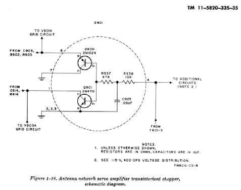
Antenna-network and servo-ampl subchassis |
| V901B | 2d phasing ampl | |||
| V902 | 3d phasing ampl | 6005/6AQ5W | 6005/6AQ5W/6098 | |
| V903A | 1st loading ampl | 5751 | 5751 | |
| V903B | 2d loading ampl | |||
| V904 | 3d loading ampl | 6005/6AQ5W | 6005/6AQ5W/6098 |
Source: TM 11-5820-295-20, TM 11-5820-295-35
Konstantinos Christoforou, 22.Nov.11