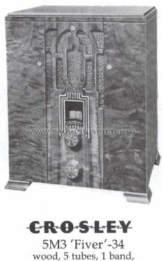
5M3 Fiver Junior
Crosley Radio Corp.; Cincinnati (OH)
- Land
- USA
- Hersteller / Marke
- Crosley Radio Corp.; Cincinnati (OH)
- Jahr
- 1934
- Kategorie
- Rundfunkempfänger (Radio - oder Tuner nach WW2)
- Radiomuseum.org ID
- 36845

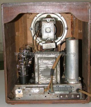
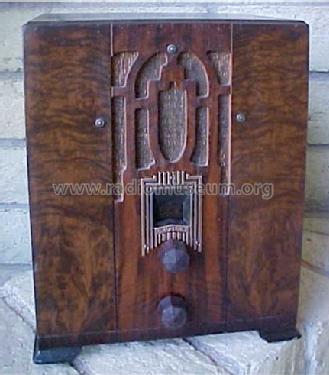
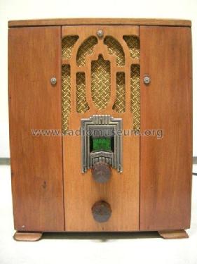
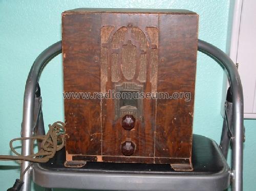
Radio from my collection. Crosley 5M3.
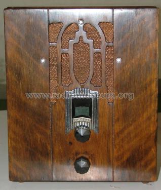
Radio from my collection. Crosley 5M3.

Kop.gen.
Ebay Nr. 190019436655 Bild bearbeitet.
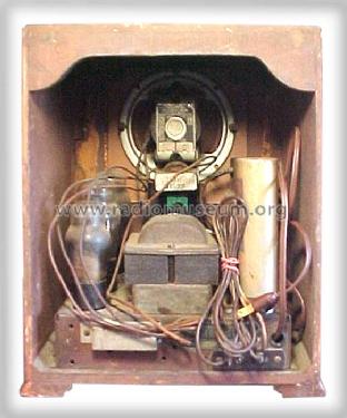
Ebay Nr. 190019436655 Bild bearbeitet.
Ebay Nr. 190019436655 Bild bearbeitet.
Ebay Nr. 190019436655 Bild bearbeitet.
Picture courtesy of eBay seller tomb715

Picture courtesy of eBay seller tomb715

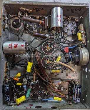
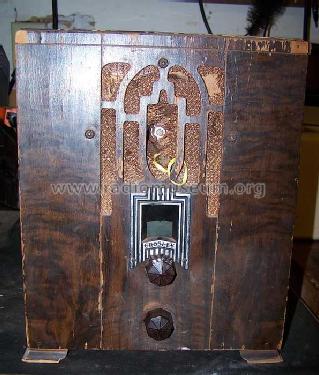
aus ebay, Verkäufer kevco12
aus ebay, Verkäufer kevco12
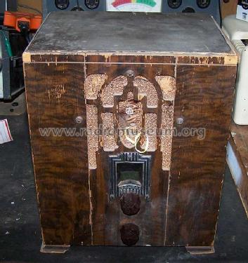

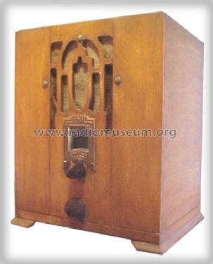
eBay item number:185813213318
eBay item number:185813213318

eBay item number:185813213318
eBay item number:185813213318

eBay item number:185813213318

eBay item number:185813213318
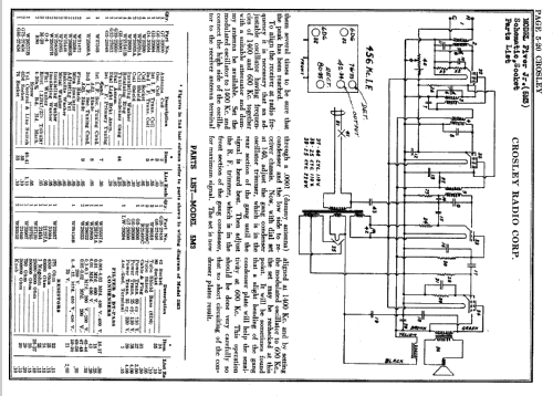
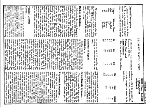
Klicken Sie auf den Schaltplanausschnitt, um diesen kostenlos als Dokument anzufordern.
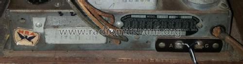
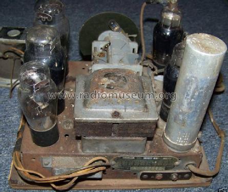
- Anzahl Röhren
- 5
- Hauptprinzip
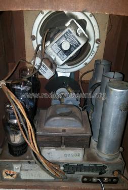
- Superhet allgemein; ZF/IF 456 kHz; Schirmgitter 1926-1935
- Anzahl Kreise
- 6 Kreis(e) AM
- Wellenbereiche
- Mittelwelle, keine anderen.
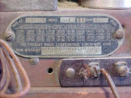
- Betriebsart / Volt
- Wechselstromspeisung
- Lautsprecher
- Dynamischer LS, mit Erregerspule (elektrodynamisch)
- Material
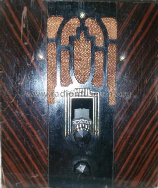
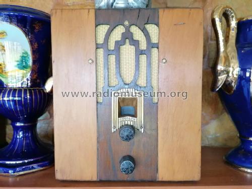
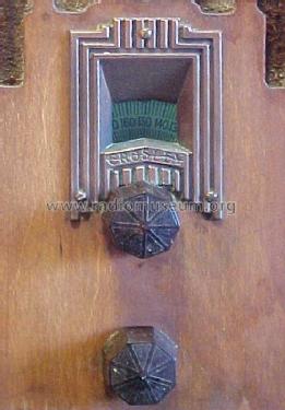
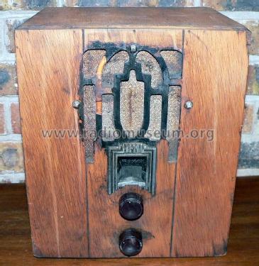
- Gerät mit Holzgehäuse
- von Radiomuseum.org
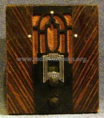
- Modell: 5M3 Fiver Junior - Crosley Radio Corp.;
- Form
- Tischgerät, Hochformat, dekoratives Gehäuse oder runde Ecken.
- Abmessungen (BHT)
- 9.8 x 11.8 x 7.6 inch / 249 x 300 x 193 mm
- Bemerkung
- Grinder calls a console, but this is definitely a table model.
- Datenherkunft extern
- Ernst Erb
- Literaturnachweis
- Table Top Radios Vol. 1 Stein 98
- Literatur/Schema (1)
- Rider's Perpetual, Volume 5 = ca. 1934 and before (page 20)
- Weitere Modelle
-
Hier finden Sie 1813 Modelle, davon 1053 mit Bildern und 1306 mit Schaltbildern.
Alle gelisteten Radios usw. von Crosley Radio Corp.; Cincinnati (OH)
Sammlungen
Das Modell 5M3 befindet sich in den Sammlungen folgender Mitglieder.
Forumsbeiträge zum Modell: Crosley Radio Corp.;: 5M3 Fiver Junior
Threads: 2 | Posts: 8
Help again., Is there anyone who has a more detailed schematic on this little radio. There are three cans that are not marked along with missing details about other caps on the schematic from nostalgia. plus a couple others caps that appear to go from ground to ground. someone played with this before me.Thanks in advance.
George Davis, 14.Mar.12
Good morning Gentlemen, I have been reading the great answers in this forum ,and now have one of my own, I am a newbe,(late starter). I am working on a crosley 5m3.. There are a couple capacitors that are marked (example) 2X .02. one positive one negitive. The positive has two lines to it. I am assuming it is double duty. Should I seperate the two and put two capacitors or just use one. Thanks in advance .(first newbe question)
George Davis, 02.Mar.12