- Country
- Italy
- Manufacturer / Brand
- Damaiter (marca / brand); ved. le note / see text
- Year
- 1949–1951 ?
- Category
- Broadcast Receiver - or past WW2 Tuner
- Radiomuseum.org ID
- 193992


Click on the schematic thumbnail to request the schematic as a free document.
- Number of Tubes
- 5
- Main principle
- Superheterodyne (common); ZF/IF 471 kHz; 2 AF stage(s); none
- Tuned circuits
- 6 AM circuit(s)
- Wave bands
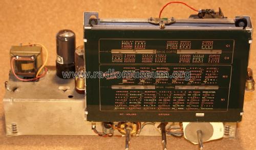
- Broadcast and Short Wave (SW).
- Power type and voltage
- Alternating Current supply (AC) / 110-220 Volt
- Loudspeaker
- Permanent Magnet Dynamic (PDyn) Loudspeaker (moving coil) - elliptical / Ø 20 cm = 7.9 inch
- Power out
- 4 W (unknown quality)
- Material
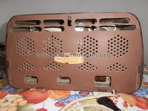
- Wooden case
- from Radiomuseum.org
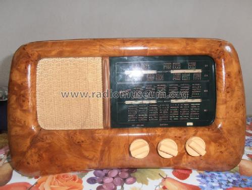
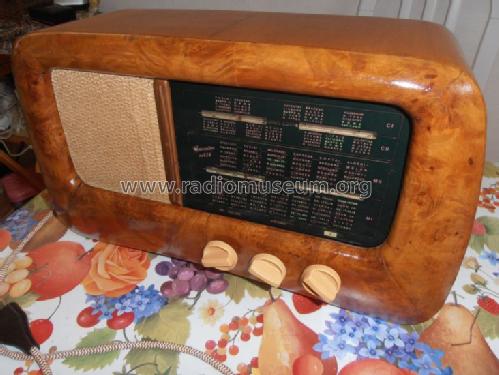
- Model: M826 - Damaiter marca / brand; ved.
- Shape
- Tablemodel, low profile (big size).
- Notes
- Stesso chassis Magnadyne S24, Kennedy 240K.
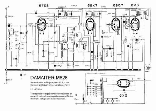
The Damaiter M826 relies on the same chassis (minor or null variations) of the Magnadyne S22 and S24 and of the Kennedy 240K. It has been designed with the purpose of lowering as much as possible production costs while preserving a relatively good sensitivity level and sound quality. The chassis, despite the use of an autotransformer, is insulated from the mains. The MW band is split (as in other Magnadyne receivers of the same period) in two parts; two SW bands are also present.
- Mentioned in
- Il Radio Libro (E.D. Ravalico) Edizioni Hoepli (13° edizione, 1952)
- Author
- Model page created by Roberto Guidorzi. See "Data change" for further contributors.
- Other Models
-
Here you find 29 models, 23 with images and 21 with schematics for wireless sets etc. In French: TSF for Télégraphie sans fil.
All listed radios etc. from Damaiter (marca / brand); ved. le note / see text
Collections
The model is part of the collections of the following members.
Forum contributions about this model: Damaiter marca /: M826
Threads: 1 | Posts: 1
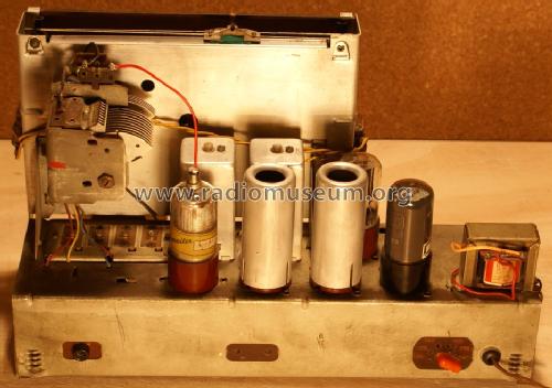
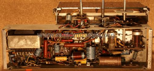
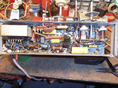
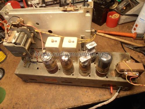
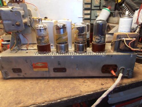
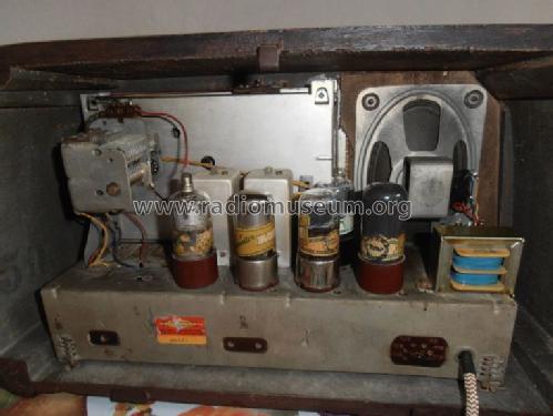
The Damaiter M826 is based on the same chassis used in Magnadyne S22, S23, S24, S32, S34 and in Kennedy K240 models; the following notes apply thus also to these sets. The M826 is a five tubes superheterodyne : 6TE8 (Osc/Mix), 6SK7 (I.F.), 6SQ7 (Det/Audio), 6V6 (Output stage), 6X5 (Rectifier). The power supply uses an autotransformer. The whole design is oriented towards reducing construction costs but remarkable attention has been paid to sensitivity and audio quality.

After the (almost certainly necessary) substitution of the electrolytic capacitors it is necessary to consider the state of paper capacitors. Every capacitor should be checked to evaluate whether the leakage current allows avoiding its substitution; most capacitors used in this set had been produced by Ducati and are resin-encapsulated. Many of them did not offer proper safety levels and very few original ones have been left in place. Their construction does not allow the insertion of new components in the old shells so that, to preserve the original look, they have been entirely rebuilt respecting the original dimensions and reprinting their labels (the following picture shows two damaged capacitors and a rebuilt one).

Proper attention must be played to the fact that, despite the use of an autotransformer, the chassis is insulated but connected to the mains by means of capacitors whose working voltage and type must be carefully considered (see the excellent article Replacing old capacitors by Emilio Ciardiello).
Another component whose substitution, when necessary, can pose some problems is the output transformer since its secondary winding is endowed with an intermediate tap used to introduce a negative feedback in the audio amplification chain. In the set shown in the pictures it had been substituted with a standard transformer and the feedback signal had been taken from the whole secondary winding.
Some resistors have a traditional ceramic-substrate structure and will almost certainly have preserved the original values. Some others are of the carbon composition type and come from the first production lines adopting this technology in Italy; they should be carefully controlled. Different sets show different percentages of resistors of the first and second types; parallel connections to obtain the desired values and power ratings are not infrequent.
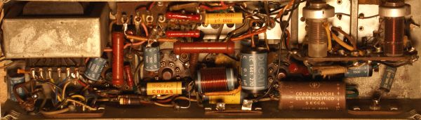
Finally the mica capacitors will probably be in good conditions; a check of the values of the padding capacitors is, however, suggested.
After the necessary substitutions of components the set can be aligned and this requires some attention on the sequence of the operations because, to simplify the overall architecture, many coils are serial-connected and the total number of possible regulations is too limited to perform a complete alignment on all bands (two SW and two MW ).
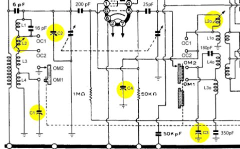
After aligning the I.F. channel (471 KHz) with standard procedures, the alignment of the SW and MW bands has been performed in the following way that refers to the notations introduced in the electrical diagram.


1) Select the SW band C I. Align the scale at 18.75 MHz using C4. Maximize the output using C2.
2) Select the SW band C II. Align the scale at 6 MHz using L2o. Maximize the output using L2.
3) Select the MW band M I. Align the scale at 1.5 MHz using C3.
4) Select the MW band M II. Maximize the gain at 857 KHz using C1.
The procedure reported above must be considered only as one among many possibilities; it has lead, however, to very satisfactory results.
Roberto Guidorzi, 20.Mar.11