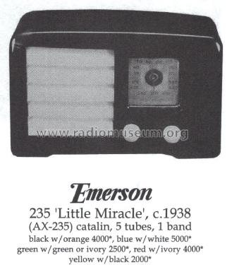
AX-235 "Little Miracle"
Emerson Radio & Phonograph Corp.; New York, NY
- Land
- USA
- Hersteller / Marke
- Emerson Radio & Phonograph Corp.; New York, NY
- Jahr
- 1938/1939
- Kategorie
- Rundfunkempfänger (Radio - oder Tuner nach WW2)
- Radiomuseum.org ID
- 70865
-
- anderer Name: Emerson Television
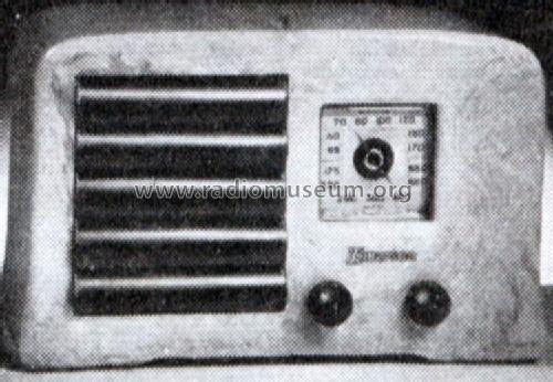
Beitman

Ebay Nr. 270102938604 Bild bearbeitet.


Quelle Bechstein

Quelle Bechstein
Under Restoration

Shop Etsy 92048433

Shop Etsy 92048433
Shop Etsy 92048433
Ebay Seller liquidchr0me Item 230776645325
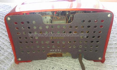
Ebay Seller liquidchr0me Item 230776645325
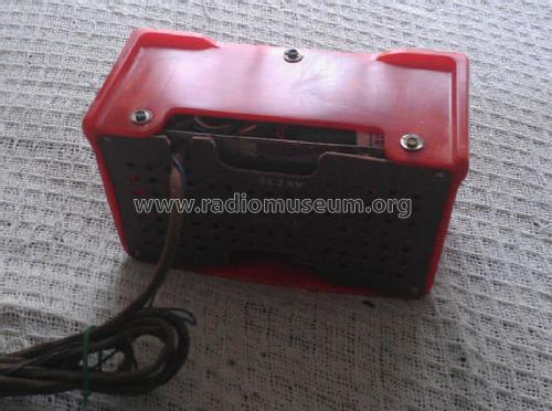
Ebay Seller liquidchr0me Item 230776645325

Ebay Seller liquidchr0me Item 230776645325


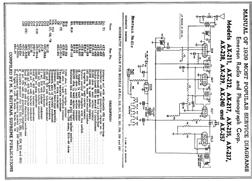
Klicken Sie auf den Schaltplanausschnitt, um diesen kostenlos als Dokument anzufordern.
- Anzahl Röhren
- 5
- Hauptprinzip
- Superhet allgemein; ZF/IF 455 kHz
- Wellenbereiche
- Mittelwelle, keine anderen.
- Betriebsart / Volt
- Allstromgerät / 105-125 Volt
- Lautsprecher
- Dynamischer LS, mit Erregerspule (elektrodynamisch) / Ø 4 inch = 10.2 cm
- Material
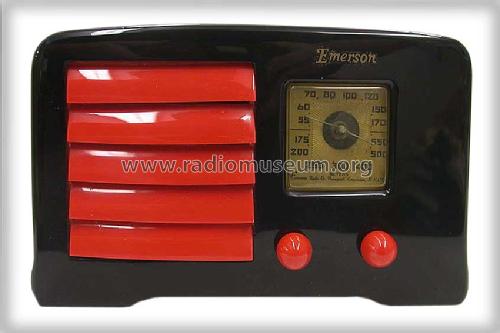
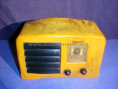
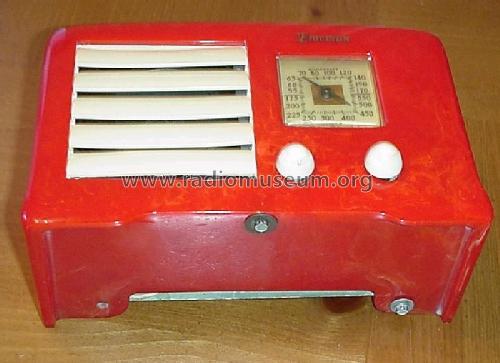
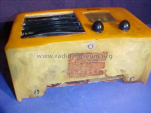
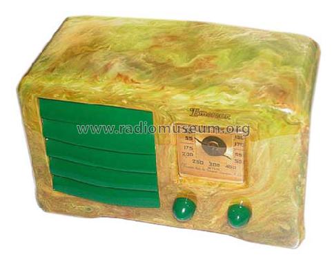
- Catalin
- von Radiomuseum.org
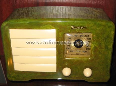
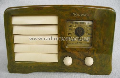
- Modell: AX-235 "Little Miracle" - Emerson Radio & Phonograph
- Form
- Tischgerät ohne Drucktasten, bis 35 cm Breite (Kleingerät, meist dekorativ. Nur für Netzbetrieb, doch Transportgriff möglich).
- Abmessungen (BHT)
- 226 x 143 x 96 mm / 8.9 x 5.6 x 3.8 inch
- Bemerkung
-
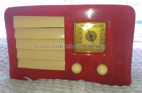
Selection of six Gem-like color combinations.
Power Consumption: 45 W.
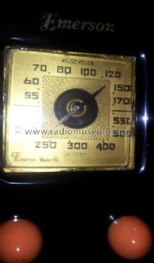
Broadcast frequency range: 540 - 1.780 kHz.
- Nettogewicht
- 2.2 kg / 4 lb 13.5 oz (4.846 lb)
- Originalpreis
- 17.95 $
- Datenherkunft
- Collector's Guide to Antique Radios 4. Edition
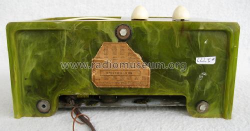
- Schaltungsnachweis
- Beitman Radio Diagrams Vol. 2, 1939
- Literaturnachweis
- Table Top Radios Vol. 1 Stein 98 (Sideli: Classic Plastic Radios)
- Literatur/Schema (3)
- Emerson Folder Form. 39-22, 2-39 for 1939.
- Autor
- Modellseite von Walter Wiesmüller † May 2012 angelegt. Siehe bei "Änderungsvorschlag" für weitere Mitarbeit.
- Weitere Modelle
-
Hier finden Sie 2088 Modelle, davon 1150 mit Bildern und 1646 mit Schaltbildern.
Alle gelisteten Radios usw. von Emerson Radio & Phonograph Corp.; New York, NY
Sammlungen
Das Modell AX-235 "Little Miracle" befindet sich in den Sammlungen folgender Mitglieder.
Forumsbeiträge zum Modell: Emerson Radio &: AX-235 "Little Miracle"
Threads: 1 | Posts: 8
I am currently restoring an example of one of these radios and I have already a fair amount of experience with Emersons. This one has me baffled at present!
The chassis is more or less as factory spec but the tuning coil T1 has been chopped about in the past probably to add LW to the bands. Im not even sure that the coil is correct however I have removed all the added parts and tried to rig up the coil as intended.
The rest of the chassis components appear to be OK and resistors etc seem to buz out fine. As I am in the UK and the sets were 110AC, the line cord (missing) had to be rewired. I do this by feeding 110VAC into the set but put a series 220R resistor in line with the heaters. This allows the HT to run plus also the LT. Im getting approx 5V across each tube heater. Little bit low but still OK.
The problem is that once powered up, the audio stage is good plus the 6Q7 stage but Im not getting any signal. Touching the caps if the 6A8 and 6K7 tubes produce a click but thats it. HT is running at 82V before the speaker field coil and 66V after. Im starting to wonder if I have a bad 6A8 but any help would be useful. What is the HT that I should get?
Anlagen
- Diagram (97 KB)
Mark Andrews, 28.Feb.11