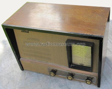
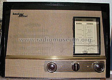
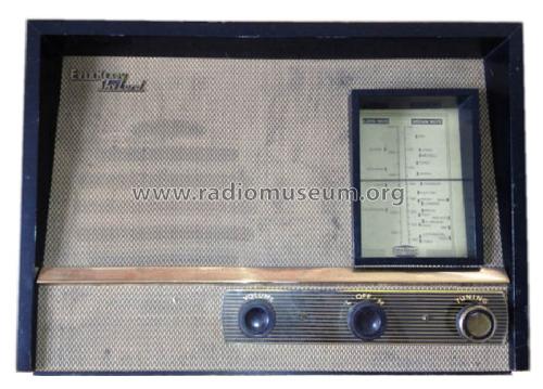
Sky Lord
Ever Ready Co. (GB) Ltd.; London
- Country
- Great Britain (UK)
- Manufacturer / Brand
- Ever Ready Co. (GB) Ltd.; London
- Year
- 1957–1962
- Category
- Broadcast Receiver - or past WW2 Tuner
- Radiomuseum.org ID
- 71999


ebay 111017991854 ID = sfg_arctic
ebay 111017991854 ID = sfg_arctic
Drive cord, rear view


Click on the schematic thumbnail to request the schematic as a free document.
- Number of Tubes
- 4
- Main principle
- Superheterodyne (common); ZF/IF 470 kHz; 2 AF stage(s)
- Tuned circuits
- 6 AM circuit(s)
- Wave bands
- Broadcast (MW) and Long Wave.
- Power type and voltage
- Dry Batteries / 1.5 & 90 Volt
- Loudspeaker
- Permanent Magnet Dynamic (PDyn) Loudspeaker (moving coil) / Ø 8 inch = 20.3 cm
- Power out
- 0.25 W (unknown quality)
- Material
- Wooden case
- from Radiomuseum.org
- Model: Sky Lord - Ever Ready Co. GB Ltd.; London
- Shape
- Tablemodel, with any shape - general.
- Notes
-
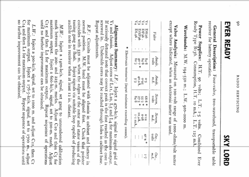
Uses Ever Ready B136 combined HT/LT 90/1.5 volt battery. The cabinet is shallower than the Ever Ready Sky Prince with the battery above the chassis, so the B137 will not fit.
Same loudspeaker/transformer arrangement and an absolutely identical circuit and chassis to the 1955 "Sky Prince", but a restyled cabinet. The alignment procedure is also identical. The Sky Prince cabinet is almost 1938 style (linear scale replacing "clock scale") despite being a 1955 Model. This is the last model to use the design and chassis originated with the Model K and the Model T (the last version of the T even used '96 series 25mA valves) K. The Sky Queen (original) and BEREC Jester/Sky King chassis is also very similar but have one less trimmer.
- External source of data
- Ever Ready Radio Servicing.
- Source of data
- Radio And Television Servicing books (R&TVS)
- Author
- Model page created by Keith Watt. See "Data change" for further contributors.
- Other Models
-
Here you find 204 models, 147 with images and 92 with schematics for wireless sets etc. In French: TSF for Télégraphie sans fil.
All listed radios etc. from Ever Ready Co. (GB) Ltd.; London
Collections
The model Sky Lord is part of the collections of the following members.
Forum contributions about this model: Ever Ready Co. GB: Sky Lord
Threads: 1 | Posts: 1
The post WWII battery valve sets using B7G miniature tubes were sold from 1946 to 1962, though the type of set was released in 1941 in the USA and by 1958 the transistor was economical for AM sets. So though these sets are relatively common and can sell for as little as 15 Euro in the UK they are now typically 60 to over 70 years old. Unlike Germany the VHF-FM battery valve sets were rare in the UK probably for reasons of cost and use. There was no VHF service till 1955 in the UK and till late 1961 in Ireland. Even then in the UK it simply duplicated the three main BBC stations till the 1970s. In Ireland there was only one VHF station after 1961, a duplication of Radio Éireann till the 1970s. The UK produced one AM/FM battery valve table model and just two portables, one of which was really a re-badged export model.
Why the Sky Lord?
It was for the dwindling number of UK and irish dwellings from 1957 to 1962 with no mains electricity as it is a table model. It was only a revision of the cabinet of the Sky Prince, dropping the ability to have the massive B137 pack. The Sky King also used the B136 pack used for the Sky Lord and was probably still on sale till 1959. It was replaced by the Sky Captain in 1961 even though Ever Ready had released transistor sets. The Sky Captain used the shorter life B141, that had been used in several more compact Ever Ready models. So my philosophy is now to try and treat the 1950s valve portables like 1930s radios. Anything visible should be the same as the original. Where feasible I leave the earth end of capacitors connected and capacitors in place, adding new ones along side under the chassis. I resist the idea of adding "FM", "Bluetooth" or any kind of sockets. Sets with a Gram or Tape input can easily be used with an external 3.5mm jack adaptor to a phone/MP3 player, €5 FM radio or €10 BT receiver.
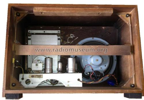
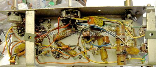
Stage One: Chassis removal
The Trader sheet for the Sky Prince gives more information than the 1958 R&TVS book for the Sky Lord. They are totally identical apart from the cabinet. Even the scale seems unchanged.
Note positions of the four wires to be unsoldered. Top green, bottom yellow on the loop aerial. From rear left, red on 2nd and blue on 4th transformer connections. Loosen the three knob grub screws. Easing spray may be needed on the screws and shafts. Warning, the label under the perspex panel is just printed heavy paper!
Stage Two: The capacitors
There are four paper dielectric capacitors, so called waxies. Three are 100nF (0.1µF) and one is 50nF (0.05µF) . A 47nF is fine. Metallized Polyester 250V to 400V are possibly the easiest and cheapest to get. Any 100V rated ceramic part will likely be fine. Tolerance isn't critical. Use 150V rated minimum for the plastic film types. Don't use vintage parts. The AGC capacitor (47nF) probably can be as low as 20V rated. The 8uF 150V electrolytic isn't critical in value or rating (as long as more than 110V DC), likely it will reform. I test such parts by cutting or unsoldering one end and applying a current limited 30V to 60V (even for 450V parts in mains radios and amps). Then watch voltage fall on a 10M input DVM. Test on a tester AFTER discharging. Less than 2 Ohms ESR and capacitance at value or higher is fine, for this application. Requirements for SMPSUs or cathode decoupling are different. Instability at high volume on a battery set usually means the ESR (Effective Series Resistance) has gone too high, even if the capacitance is OK.
The DMM or a capacitor meter is no use at all to test leakage of paper dielectric. Only military grade hermetically sealed types with the seal intact surviive more than t0 to 15 years. The makers knew this from 1930s to 1950s. The paper or Waxies or Hunts Moldseal (Paper in Oil is the same thing really) simply don't last as the oil / wax/ paraffin gradually absorbs water and the leakage increases. You need over 100V and a micro-ammeter to measure it. The series resistances are high, so the effect is to reduce the g2 (screen grid) voltage to a fraction of the original, killing the gain. Any between and Anode and a grid are disastrous even at a fraction of a microamp due to the very high impedance of a grid and circuit. Many sets have the audio drive to speaker transformer burnt out. Fortunately this chassis series usually uses a ceramic capacitor between the DAF96 anode and DL96 grid. The ceramic capacitors really only ever fail due to lightning on a aerial circuit or in applications with a high pulsed voltage, like a valve TV LOPT. Mica capacitors rarely fail either, usually only from mechanical damage. Polystyrene replaced mica and are easily damaged by soldering heat or mechanically.
Corrosion
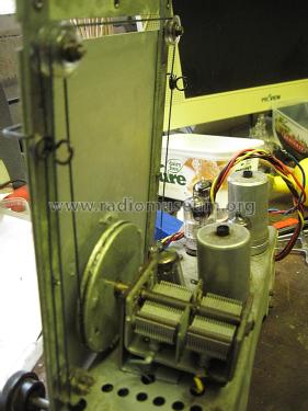
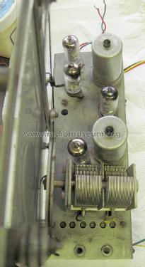
Likely the B7G sockets and the switch need switch cleaner. The bearings on the tuner and all the drive cord moving parts need oiled. Do not get oil or switch cleaner on the tuning vanes as it dramatically changes the capacitance. You can use IPA or other alcohols to wash them if that happens. Then wait for them to dry. If the cord hasn't snapped, it might. The springs either side of the scale cursor rust and this damages the cord. The drive spindle may rust too and damage the cord.
More to come
Next we will look at fitting a drive cord, then alignment and finally the cabinet. A replica battery pack can be economically run using two Alkaline D cells in parallel for LT and 60 x budget Alkaline AA cells for HT. This gives similar capacity to the B136 pack and fits the replica case. Using 10 x PP3 packs isn't economic. Don't use a viintage battery eliminator. They are not regulated nor safe. A home built psu should be about 1.35V LT and 82V HT (both 5%). Mullard Philips recommendations. Fuse the LT and HT inside the battery pack or PSU.
Michael Watterson, 06.Sep.18