Capehart 35P7 Ch= P-7
Farnsworth Television & Radio Corp. - see also Capehart
- Produttore / Marca
- Farnsworth Television & Radio Corp. - see also Capehart
- Anno
- 1948–1951
- Categoria
- Radio (o sintonizzatore del dopoguerra WW2)
- Radiomuseum.org ID
- 40036


von Josh Fisher

SAMS
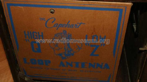
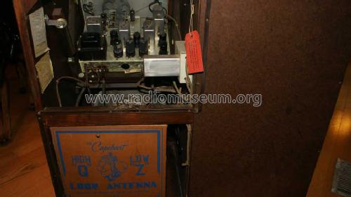
Capehart 35P7 Antenna
Capehart 35P7 Back

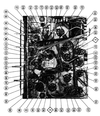
Capehart 35P7 Chassis Top
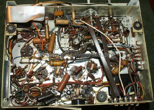
Capehart 35P7 Chassis Bottom

Capehart 35P7 Scale

Capehart 35P7 Phonograph Pickup

USA_Farnsworth_capehart_35P7_Type_Label
Clicca sulla miniatura dello schema per richiederlo come documento gratuito.
- Numero di tubi
- 12
- Principio generale
- Supereterodina con stadio RF; ZF/IF 455/10700 kHz
- N. di circuiti accordati
- 9 Circuiti Mod. Amp. (AM) 11 Circuiti Mod. Freq. (FM)
- Gamme d'onda
- Onde medie (OM) e MF (FM).
- Particolarità
- Cambiadischi
- Tensioni di funzionamento
- Alimentazione a corrente alternata (CA) / 60 Hz, 117V = 110 -120 Volt
- Altoparlante
- AP magnetodinamico (magnete permanente e bobina mobile) / Ø 11.875 inch = 30.2 cm
- Materiali
- Mobile in legno
- Radiomuseum.org
- Modello: Capehart 35P7 Ch= P-7 - Farnsworth Television & Radio
- Forma
- Console di qualsiasi tipo
- Annotazioni
-
Capehart model 35P7 is an AC operated combination phono-radio, AM-FM superheterodyne receiver with loop antenna.
According to SAMS Photofact Date 6-51, set 135, folder 4, the following Capehart models, made by Farnsworth Television and Radio Corp., fort Wayne, Indiana use the following chassis: 35P7 = chassis P-7 (including tube 6SC7 for the bias cell), 1002F, 1003M and 1004B = chassis P-8 with a different loop antenna and treble tone control instead of bass tone control. The Record Changer here is a P-71 and there is a built in AM loop antenna.
See here the "Common information for the Capehart model pages for the 1930s and 1940s". Here the cabinet style is missing.
- Fonte esterna dei dati
- Ernst Erb
- Riferimenti schemi
- Rider's Perpetual, Volume 19 = 1949 and before
- Letteratura / Schemi (1)
- Photofact Folder, Howard W. SAMS (Date 6-1951, Set 135, Folder 4)
- Altri modelli
-
In questo link sono elencati 402 modelli, di cui 286 con immagini e 328 con schemi.
Elenco delle radio e altri apparecchi della Farnsworth Television & Radio Corp. - see also Capehart
Collezioni
Il modello Capehart 35P7 fa parte delle collezioni dei seguenti membri.