- Country
- United States of America (USA)
- Manufacturer / Brand
- General Electric Co. (GE); Bridgeport CT, Syracuse NY
- Year
- 1941/1942
- Category
- Broadcast Receiver - or past WW2 Tuner
- Radiomuseum.org ID
- 42460
-
- Brand: Musaphonic


Copy gen. durch Steve Tardi Radio Attic


Scanned from the Radio Retailing July 1941.
Click on the schematic thumbnail to request the schematic as a free document.
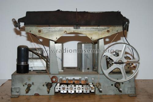
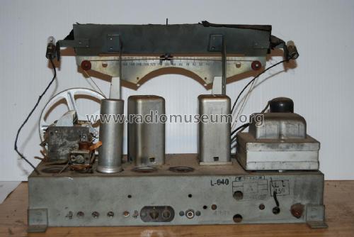
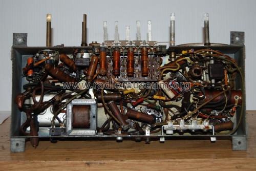
- Number of Tubes
- 6
- Main principle
- Superheterodyne (common); ZF/IF 455 kHz
- Wave bands
- Broadcast plus 2 Short Wave bands.
- Power type and voltage
- Alternating Current supply (AC) / 110-125 Volt
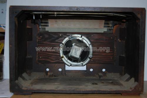
- Loudspeaker
- Permanent Magnet Dynamic (PDyn) Loudspeaker (moving coil) / Ø 5 inch = 12.7 cm
- Power out
- 4.6 W (unknown quality)
- Material
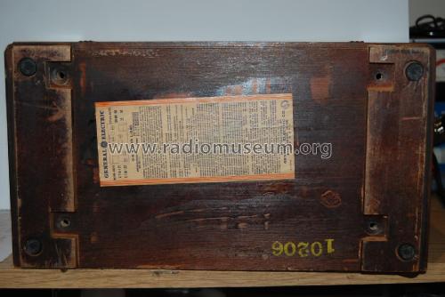
- Wooden case
- from Radiomuseum.org
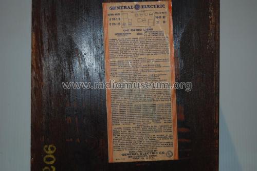
- Model: L-640 - General Electric Co. GE;
- Shape
- Tablemodel with Push Buttons.
- Dimensions (WHD)
- 15.5 x 10.5 x 8.5 inch / 394 x 267 x 216 mm
- Notes
- Dial lamp: 2 Mazda Nº44.
- Price in first year of sale
- 44.95 $
- External source of data
- Ernst Erb
- Source of data
- Collector's Guide to Antique Radios 4. Edition
- Circuit diagram reference
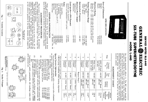
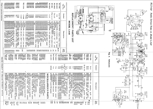
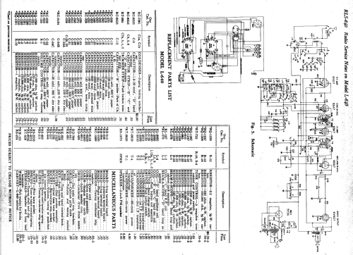
- Rider's Perpetual, Volume 13 = 1942 and before
- Literature/Schematics (1)
- General Electric Radio Service Notes 1939-1942
- Literature/Schematics (2)
- Radio Retailing (Radio & Television R.) (July 1941.)
- Literature/Schematics (3)
- Machine Age to Jet Age II (page 145.)
- Other Models
-
Here you find 2962 models, 2174 with images and 2074 with schematics for wireless sets etc. In French: TSF for Télégraphie sans fil.
All listed radios etc. from General Electric Co. (GE); Bridgeport CT, Syracuse NY
Collections
The model L-640 is part of the collections of the following members.
Forum contributions about this model: General Electric Co.: L-640
Threads: 2 | Posts: 4
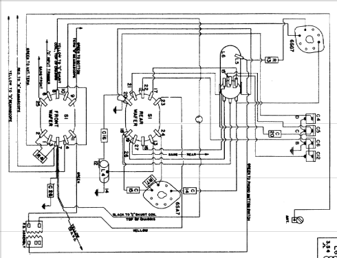
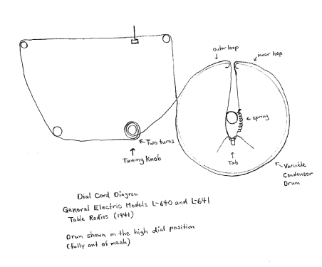
Upon further investigation, I have determined that the dial cord routing I found on the chassis is correct. If it still slips a bit, you just have to keep tightening the connection to the spring until it stops. I have posted a hand drawing of the routing for the benefit of anyone who obtains an L-640 (and most likely, also an L-641) where the dial cord is broken or missing.
Jeffrey Gill, 21.Mar.14
I am very much in need of a dial stringing diagram for a General Electric model L-640 3-band table radio from 1941. For some reason, it never made it into the schematic pages here from the General Electric Radio Service Notes 1939-1942, nor has it made it into the Riders. Model L-641 uses the same variable condensor drum assembly, GE radio part number RD-426, but no dial stringing diagram appears for that model either.
Is it possible that the diagram does appear in the GE Radio Service Notes, but on a page that is not contiguous with the schematics for the L-640 and L-641, so it was missed? If anyone has a copy of those service notes, I'd appreciate it if they could check and let me know.
Jeffrey Gill, 21.Mar.14