Majestic Ch= 180
Grigsby-Grunow (-Hinds) Co. (Majestic pre 1933); Chicago (IL)
- Produttore / Marca
- Grigsby-Grunow (-Hinds) Co. (Majestic pre 1933); Chicago (IL)
- Anno
- 1928
- Categoria
- Radio (o sintonizzatore del dopoguerra WW2)
- Radiomuseum.org ID
- 43607

Clicca sulla miniatura dello schema per richiederlo come documento gratuito.
- Numero di tubi
- 9
- Principio generale
- A circuiti accordati (amplif. diretta) senza reazione; 3 Stadi BF; Neutrodina (con neutrocondensatore)
- N. di circuiti accordati
- 4 Circuiti Mod. Amp. (AM)
- Gamme d'onda
- Solo onde medie (OM).
- Tensioni di funzionamento
- Alimentazione a corrente alternata (CA) / 90-130 Volt
- Altoparlante
- AP elettrodinamico (bobina mobile e bobina di eccitazione/di campo)
- Materiali
- Mobile di metallo
- Radiomuseum.org
- Modello: Majestic Ch= 180 - Grigsby-Grunow -Hinds Co.
- Forma
- Chassis o in scatola da montaggio
- Annotazioni
-
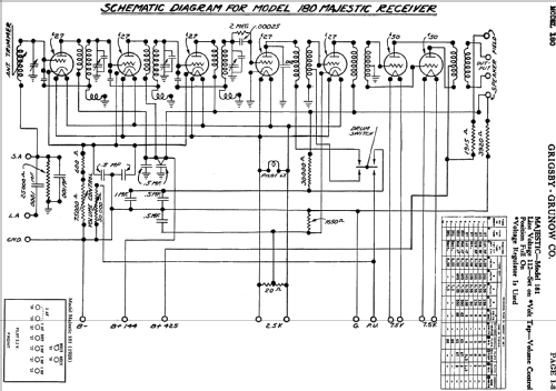
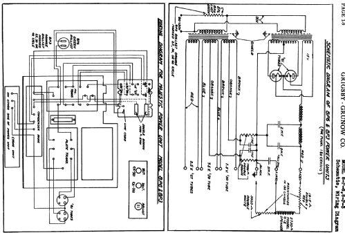
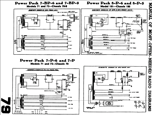
Push-pull af output stage; using the 8P6 or 8P3 power unit; chassis for Majestic model 181.
This radio is a cascade of 3 individual TRF stages, each with its own feedback coil forming a Wheatstone bridge acting as a Hazeltine neutralization for the triode (described as the RFL circuit in contemporary sources). The feedback polarity is reversed with respect to the signal polarity through the Cag Miller-capacitance, in effect neutralising the triode tendency to oscillate.
The antenna circuit has a separate tuning coil, to be readjusted with each tuned frequency.
The tuning scale is graduated with 2 scales: One in frequency from 550 to 1500 kHz and the other as a linear scale from 0 to 100.
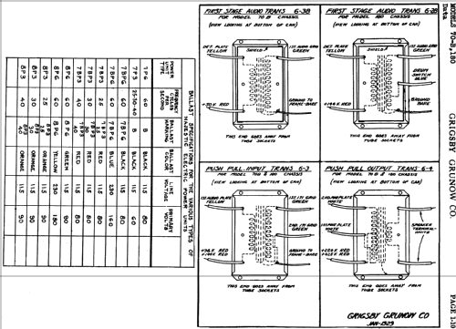
LF coupling between stages is done by transformers - Push-pull output.
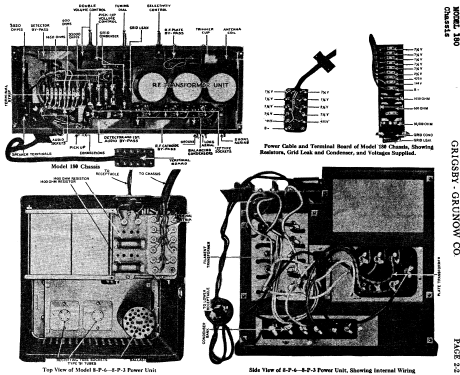
The unit contains a separate 8P6 or 8P3 power supply unit with individual transformers for the filaments and the 425 Volt anode supply. A current regulator is included in the primary circuit of the power transformers to compensate for mains voltage changes between 90 and 130 Volt AC.
- Fonte esterna dei dati
- Ernst Erb
- Riferimenti schemi
- Rider's Perpetual, Volume 1 = 1931/1934 (for 1919-1931)
- Letteratura / Schemi (1)
- Rider's Perpetual, Volume 2 = 1932 and before
- Altri modelli
-
In questo link sono elencati 201 modelli, di cui 123 con immagini e 157 con schemi.
Elenco delle radio e altri apparecchi della Grigsby-Grunow (-Hinds) Co. (Majestic pre 1933); Chicago (IL)