Majestic Ch= 180
Grigsby-Grunow (-Hinds) Co. (Majestic pre 1933); Chicago (IL)
- Land
- USA
- Hersteller / Marke
- Grigsby-Grunow (-Hinds) Co. (Majestic pre 1933); Chicago (IL)
- Jahr
- 1928
- Kategorie
- Rundfunkempfänger (Radio - oder Tuner nach WW2)
- Radiomuseum.org ID
- 43607

Klicken Sie auf den Schaltplanausschnitt, um diesen kostenlos als Dokument anzufordern.
- Anzahl Röhren
- 9
- Hauptprinzip
- Geradeaus ohne Rückkopplung; 3 NF-Stufe(n); Neutrodyne
- Anzahl Kreise
- 4 Kreis(e) AM
- Wellenbereiche
- Mittelwelle, keine anderen.
- Betriebsart / Volt
- Wechselstromspeisung / 90-130 Volt
- Lautsprecher
- Dynamischer LS, mit Erregerspule (elektrodynamisch)
- Material
- Metallausführung
- von Radiomuseum.org
- Modell: Majestic Ch= 180 - Grigsby-Grunow -Hinds Co.
- Form
- Chassis - Einbaugerät
- Bemerkung
-
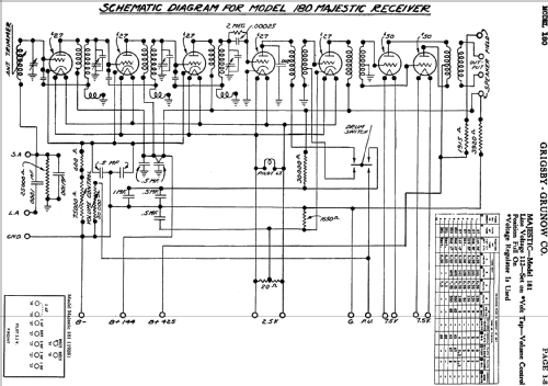
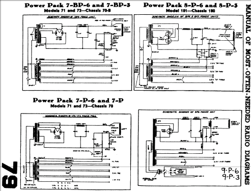
Push-pull af output stage; using the 8P6 or 8P3 power unit; chassis for Majestic model 181.
This radio is a cascade of 3 individual TRF stages, each with its own feedback coil forming a Wheatstone bridge acting as a Hazeltine neutralization for the triode (described as the RFL circuit in contemporary sources). The feedback polarity is reversed with respect to the signal polarity through the Cag Miller-capacitance, in effect neutralising the triode tendency to oscillate.
The antenna circuit has a separate tuning coil, to be readjusted with each tuned frequency.
The tuning scale is graduated with 2 scales: One in frequency from 550 to 1500 kHz and the other as a linear scale from 0 to 100.
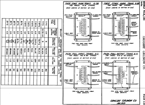
LF coupling between stages is done by transformers - Push-pull output.
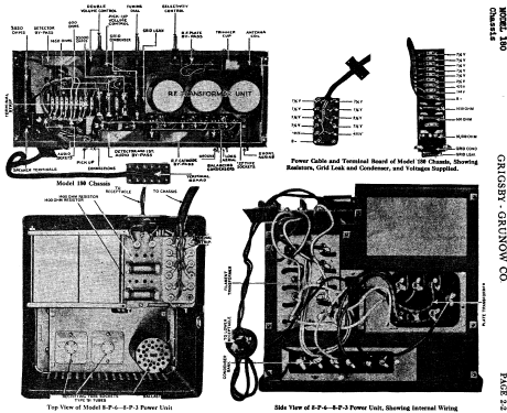
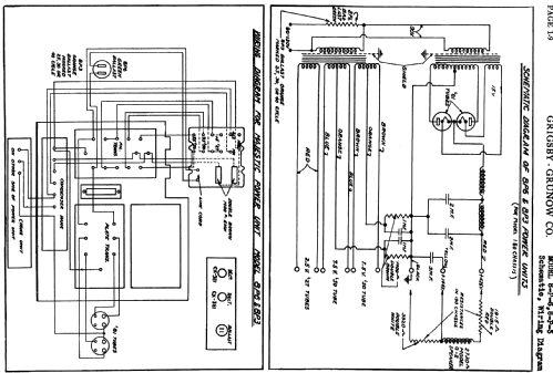
The unit contains a separate 8P6 or 8P3 power supply unit with individual transformers for the filaments and the 425 Volt anode supply. A current regulator is included in the primary circuit of the power transformers to compensate for mains voltage changes between 90 and 130 Volt AC.
- Datenherkunft extern
- Ernst Erb
- Schaltungsnachweis
- Rider's Perpetual, Volume 1 = 1931/1934 (for 1919-1931)
- Literatur/Schema (1)
- Rider's Perpetual, Volume 2 = 1932 and before
- Weitere Modelle
-
Hier finden Sie 201 Modelle, davon 123 mit Bildern und 157 mit Schaltbildern.
Alle gelisteten Radios usw. von Grigsby-Grunow (-Hinds) Co. (Majestic pre 1933); Chicago (IL)