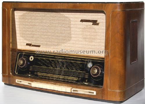
Konzertgerät 5040GW/3D
Grundig (Radio-Vertrieb, RVF, Radiowerke); Fürth/Bayern
- País
- Alemania
- Fabricante / Marca
- Grundig (Radio-Vertrieb, RVF, Radiowerke); Fürth/Bayern
- Año
- 1954/1955
- Categoría
- Radio - o Sintonizador pasado WW2
- Radiomuseum.org ID
- 2041
-
- alternative name: Grundig Portugal || Grundig USA / Lextronix


Haga clic en la miniatura esquemática para solicitarlo como documento gratuito.
- Numero de valvulas
- 10
- Principio principal
- Superheterodino con paso previo de RF; ZF/IF 468/10700 kHz; 3 Etapas de AF
- Número de circuitos sintonía
- 11 Circuíto(s) AM 11 Circuíto(s) FM
- Gama de ondas
- OM, OL, más de dos OC y FM
- Tensión de funcionamiento
- Red: Aparato AC/DC. / 110; 125; 220; 240 Volt
- Altavoz
- 4 Altavoces
- Potencia de salida
- 8 W (unknown quality)
- Material
- Madera
- de Radiomuseum.org
- Modelo: Konzertgerät 5040GW/3D - Grundig Radio-Vertrieb, RVF,
- Forma
- Sobremesa de botonera.
- Ancho, altura, profundidad
- 706 x 444 x 318 mm / 27.8 x 17.5 x 12.5 inch
- Anotaciones
- Grundig Konzertgerät 5040GW/3D hat im Gegensatz zum Wechselstrom-Modell 5040W/3D keine Motorabstimmung. Additive Triodenmischung für die AM-Bereiche. Der VDRG-Katalog 1954/55 führt irrtümlich UF89 als UKW-Vorstufe, lediglich 1x UL41 als Endstufe.
- Peso neto
- 17.3 kg / 38 lb 1.7 oz (38.106 lb)
- Precio durante el primer año
- 565.00 DM
- Procedencia de los datos
- HdB d.Rdf-& Ferns-GrH 1954/55 / Radiokatalog Band 1, Ernst Erb
- Documentación / Esquemas (1)
- -- Schematic
- Otros modelos
-
Donde encontrará 6251 modelos, 5496 con imágenes y 4255 con esquemas.
Ir al listado general de Grundig (Radio-Vertrieb, RVF, Radiowerke); Fürth/Bayern
Colecciones
El modelo Konzertgerät es parte de las colecciones de los siguientes miembros.
Contribuciones en el Foro acerca de este modelo: Grundig Radio-: Konzertgerät 5040GW/3D
Hilos: 2 | Mensajes: 2
I am restoring a Grundig 5040W/3D and want to share photographs and what I have learned. I have uploaded some photographs from the initial steps of restoration. I used schematics and forum information from radiomuseum.org, thank you!
Here is what I have done so far:
Replaced almost ALL capacitors - most of the paper capacitors were bad, leaky or out of tolerance. They have been replaced with modern capacitors, some of them were replaced with "Orange Drop" capacitors (see photos). Special consideration given to any coupling capacitors such as the one that drives the grid of the EL-12 tube. A shorted or leaky capacitor here will place positive voltage on the grid causing the tube to conduct heavily and over heat. Evidence is seen in the cathode resistor of the EL-12 which may be burned or actually smoke!
Replaced selenium rectifier with modern silicon rectifiers - the original rectifier in the black can (probably selenium) had too much resistance and over heated, so the high voltages to the tubes was too low. Replaced with four 1KV 1A silicon diodes (see photo). The set really came alive after that! I left the old rectifier on the chassis and simply clipped its leads to preserve as much of the original look as possible.
Replaced some weak tubes. I used a tube tester to identify bad tubes and replaced them. All except the EL-12 and EF804 have American equivalents.
The full resolution (large) photos of the project are available on Photobucket at this LINK.
I will try to post more information as the project continues.
James Miller
James Miller, 16.Dec.11
http://www.radiomuseum.org/forum/additive_mischschaltungen_in_den_am_wellenbereichen.html
finden Sie ausführliche Informationen zum Thema Additive Mischung in den AM-Bereichen.
Andreas Steinmetz, 09.Jun.05