Majestic 4085 3D (USA)
Grundig (Radio-Vertrieb, RVF, Radiowerke); Fürth/Bayern
- País
- Alemania
- Fabricante / Marca
- Grundig (Radio-Vertrieb, RVF, Radiowerke); Fürth/Bayern
- Año
- 1956/1957
- Categoría
- Radio - o Sintonizador pasado WW2
- Radiomuseum.org ID
- 90974
-
- alternative name: Grundig Portugal || Grundig USA / Lextronix
Lange
Lange
eBay - from an old auction 2007 (see prices)
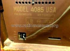
Bild von Wolfgang Bauer.
Haga clic en la miniatura esquemática para solicitarlo como documento gratuito.
- Numero de valvulas
- 7
- Numero de transistores
- Semiconductores
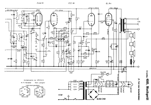
- B250C100
- Principio principal
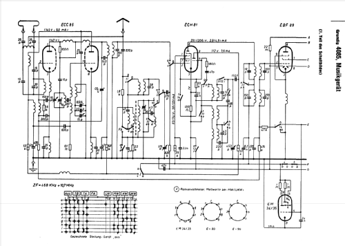
- Superheterodino en general; ZF/IF 468 kHz; Modelo de Exportacion
- Número de circuitos sintonía
- 8 Circuíto(s) AM 13 Circuíto(s) FM
- Gama de ondas
- OM, dos OC y FM
- Tensión de funcionamiento
- Red: Corriente alterna (CA, Inglés = AC)
- Altavoz
- 3 Altavoces
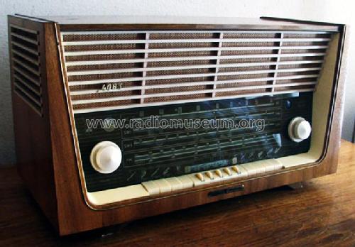
- Material
- Madera
- de Radiomuseum.org
- Modelo: Majestic 4085 3D - Grundig Radio-Vertrieb, RVF,
- Forma
- Sobremesa de botonera.
- Ancho, altura, profundidad
- 650 x 360 x 310 mm / 25.6 x 14.2 x 12.2 inch
- Anotaciones
-
This is the export model of Grundig Musikgerät 4085 but with twice shortwave instead of longwave.
Separate tuning pointers, one for AM/SW and one for FM.
Majestic 4085-3D works with a huge oval woofer with die cast frame and two side mounted mid tweeters.
- Peso neto
- 14.8 kg / 32 lb 9.6 oz (32.599 lb)
- Autor
- Modelo creado por Ernst Erb. Ver en "Modificar Ficha" los participantes posteriores.
- Otros modelos
-
Donde encontrará 6250 modelos, 5496 con imágenes y 4251 con esquemas.
Ir al listado general de Grundig (Radio-Vertrieb, RVF, Radiowerke); Fürth/Bayern
Contribuciones en el Foro acerca de este modelo: Grundig Radio-: Majestic 4085 3D
Hilos: 2 | Mensajes: 7
Hello,
I am trying to restore a Grundig Majestic model 4085 (USA version). The glass alreadt has a crack by the knob on the lower right. I can get the knobs off, but how to you remove from case? Do you pry the buttons off on the bottom before trying to slide chassis out? Thanks. This is the first radio I am rebuilding.
Chip
Chip Eckardt, 26.Oct.23
Upon restoring this radio, I discovered that there was hardly any tone coming out of the speakers, when I placed the Soviet equivalent of the EL84, a 6P14P tube/valve.
Turning the radio off immediately, and then turning it on again, using a Telefunken EL84 tube, I was able to get satisfactory tone from the radio again!
Naturally, I thought something was defective with the 6P14P tube, but to my astonishment it tested excellent on my tube tester. I then assumed that this tube might have the same issues a 7189 tube would have for this radio, but the pinout and specs are virtually identical for 6P14P and EL84.
I then proceeded to look at my various schematics for this radio, and discovered that the 47K resistor that is supposed to be connected to pin 2, was connected instead to pin 1 on my radio. With amazement, I proceeded to see where the same 47K resitor was soldered to on my parts radio (same exact Grundig radio for export), and it is soldered on pin 1, instead of where it is supposed to be soldered, on pin 2!
My question is, was this intended by the manufacturer, or is it an assembly line error?
Anexos
- EL84 socket (117 KB)
Omer Suleimanagich, 21.Apr.11