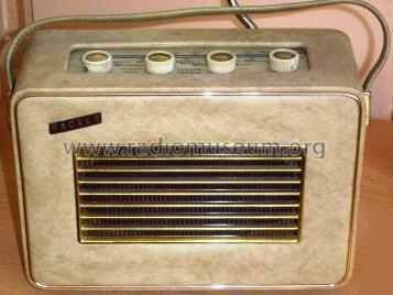
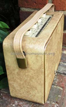
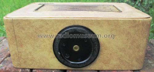
Herald RP10
Hacker Radio Ltd., Maidenhead
- Land
- Grossbritannien (UK)
- Hersteller / Marke
- Hacker Radio Ltd., Maidenhead
- Jahr
- 1960–1963
- Kategorie
- Rundfunkempfänger (Radio - oder Tuner nach WW2)
- Radiomuseum.org ID
- 79491
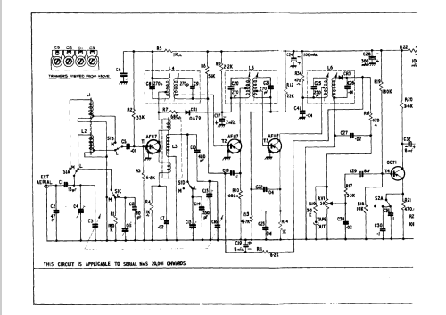
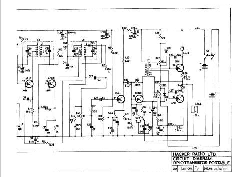
Klicken Sie auf den Schaltplanausschnitt, um diesen kostenlos als Dokument anzufordern.
- Anzahl Transistoren
- 7
- Halbleiter
- Hauptprinzip
- Superhet allgemein; ZF/IF 470 kHz
- Wellenbereiche
- Langwelle, Mittelwelle (LW+MW).
- Betriebsart / Volt
- Trockenbatterien / 2 x 9 Volt
- Lautsprecher
- Dynamischer (permanent) Ovallautsprecher / Ø 8 inch = 20.3 cm
- Belastbarkeit / Leistung
- 1 W (Qualität unbekannt)
- Material
- Leder / Stoff / Plastic / Segeltuch über div. Material
- von Radiomuseum.org
- Modell: Herald RP10 - Hacker Radio Ltd., Maidenhead
- Form
- Reisegerät > 20 cm (netzunabhängig betreibbar)
- Abmessungen (BHT)
- 12 x 8.5 x 4.5 inch / 305 x 216 x 114 mm
- Bemerkung
-
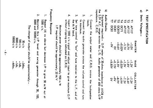
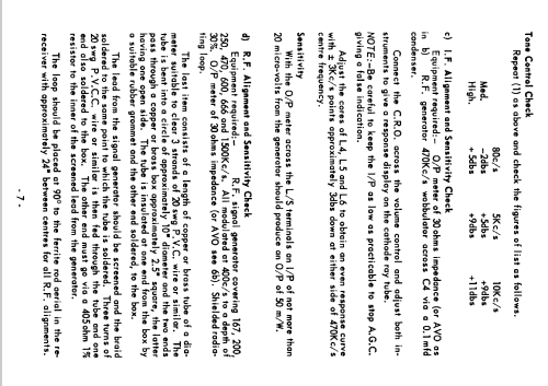
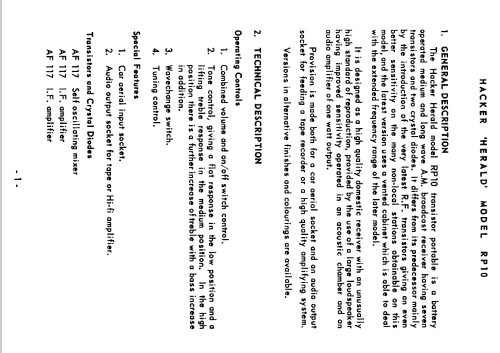
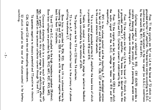
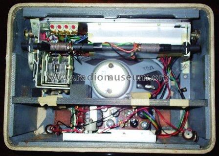
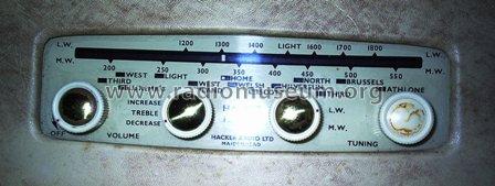
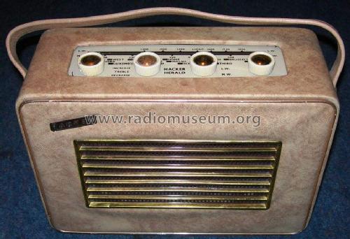
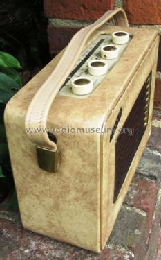
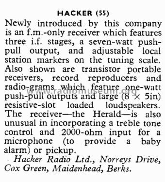
The Herald seven-transistor portable receiver. Interesting features of this are a specially-loaded large (8" x 5") loudspeaker, a one-watt push-pull output, and three-position tone control.
Sockets are provided for an external aerial for use in a car and for connecting a microphone for using the receiver as a Baby Alarm.Up to s/n 20000 Ediswan transistors fitted.
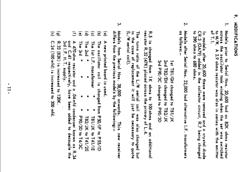
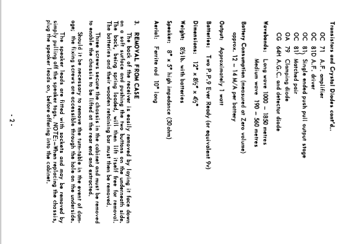
April 1962 s/n 20001 onwards chassis revised, Transistors: 3 x AF117, OC71, OC81D 2 x OC81.
- Nettogewicht
- 2 kg / 4 lb 6.5 oz (4.405 lb)
- Literaturnachweis
- Wireless World (The), London (WW, 79) (Sep 1960, Page 442.)
- Literatur/Schema (1)
- -- Original-techn. papers.
- Autor
- Modellseite von Juan Antonio Pardo-Alonso angelegt. Siehe bei "Änderungsvorschlag" für weitere Mitarbeit.
- Weitere Modelle
-
Hier finden Sie 56 Modelle, davon 56 mit Bildern und 23 mit Schaltbildern.
Alle gelisteten Radios usw. von Hacker Radio Ltd., Maidenhead
Sammlungen
Das Modell Herald befindet sich in den Sammlungen folgender Mitglieder.
Forumsbeiträge zum Modell: Hacker Radio Ltd.,: Herald RP10
Threads: 1 | Posts: 1
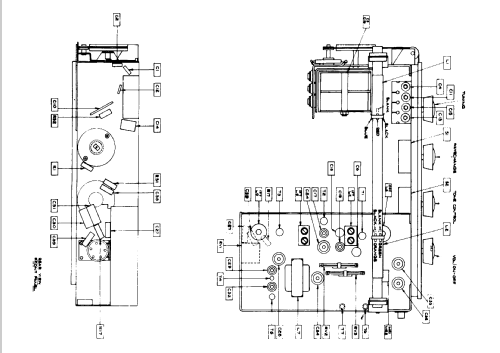
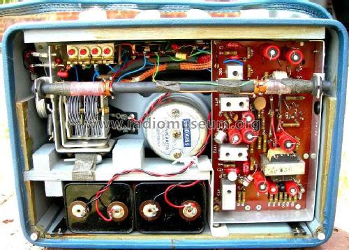
Hi can you tell me where the 6 pins from the amp board go to I'm attempting to use the amp from a RP10 to repair a RP 38a I know the position on the RP38 (their printed on the board) but on the RP10 there's only numbers 1 to 6
Eddie Stevenson, 04.Aug.20
