Beehive 11-4F Ch= 11-4
Kriesler Radio Company; Newtown (Sydney)
- Pays
- Australie
- Fabricant / Marque
- Kriesler Radio Company; Newtown (Sydney)
- Année
- 1946–1948
- Catégorie
- Radio - ou tuner d'après la guerre 1939-45
- Radiomuseum.org ID
- 297572


Cliquez sur la vignette du schéma pour le demander en tant que document gratuit.
- No. de tubes
- 4
- Principe général
- Super hétérodyne (en général); FI/IF 455 kHz; Reflex
- Gammes d'ondes
- PO et OC
- Tension / type courant
- Alimentation Courant Alternatif (CA) / 220-240 Volt
- Haut-parleur
- HP dynamique à aimant permanent + bobine mobile
- Matière
- Boitier en bakélite
- De Radiomuseum.org
- Modèle: Beehive 11-4F Ch= 11-4 - Kriesler Radio Company;
- Forme
- Modèle de table sans poussoirs, modèle cheminée
- Remarques
-
Kriesler advertised this set & other post-war models as a "Sealed Radio". Solder joints were marked to prevent unauthorised servicing & tampering.
Walnut Bakelite cabinet. Also available in various colours for 1 Guinea (£1/1/-) extra. Price in WA for standard Walnut model, £19/8/6.
There are 36 variants of this model:
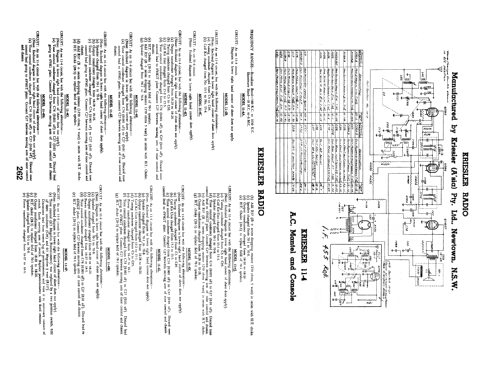
- CIRCUIT: As on 11-4 circuit but with the following alterations:- (Note: Enclosed diagram in lower right hand corner does apply).
- Speaker changed from 70-1 to 70-8.
- Output transformer changes from from 18-28 to 18-26.
- Tone control condenser changed from C74 (0.001 μF) to C27 (0.01 μF). Discard tone control lead to 6V6GT plate. Connect C27 between moving arm of tone control and chassis.
- Add R37 (B + series dropping resistor 1250 Ω, 5 watt) in series with H.T. choke.
- H.T. Choke (28-3) to replace field of 80-1 speaker.
- COIL KIT: Part No. 15-1 (S.C. Tuning Condenser).
- DIAL GLASSES: Part No. 50-1 (Country stations). Part No. 50-2 (Local stations).
- SPEAKER: Part No. 70-8 (5" Permanent magnet type).
- OUTPUT TRANSFORMER: Part No. 18-26.
- POWER TRANSFORMER: Part No. 18-27 (H.T.: 325v each side of centre tap).
PROCEDURE FOR REMOVING CHASSIS FROM CABINET:
- Remove knobs.
- Invert receiver.
- Remove base by breaking seal and unscrewing 4 x 3/16" screws in base of cabinet.
- Remove 4 x 3/16" nuts, situated in the inside corners of the chassis.
- Lay receiver on its back with spindles facing upwards.
- Place one hand each side the of chassis. With the forefingers, exert a downward pressure on the front panel, at the same time withdrawing the chassis from the cabinet.
CHASSIS NUMBERS:
Every receiver that leaves the Kriesler factory is given two chassis numbers.
The "Production" chassis number is stamped on a card. The card is riveted to the main chassis in such a location that the number is able to be read without removing the chassis from the cabinet. The "Production" chassis number is the number that should be quoted, together with the model number, when making enquiries.
The second chassis number (Prefix "0") is stamped into the metal chassis to provide a permanent record.
Both the abovementioned chassis numbers are recorded at the factory.
- Prix de mise sur le marché
- 18.90 AUS £
- Schémathèque (1)
- - - Manufacturers Literature (Kriesler Technical Service Instructions.)
- Schémathèque (2)
- Australian Official Radio Service Manual AORSM (Volume 5, 1947, Page 188 & Volume 6, 1948, Page 262.)
- Auteur
- Modèle crée par Martin Kent. Voir les propositions de modification pour les contributeurs supplémentaires.
- D'autres Modèles
-
Vous pourrez trouver sous ce lien 898 modèles d'appareils, 462 avec des images et 436 avec des schémas.
Tous les appareils de Kriesler Radio Company; Newtown (Sydney)