Beehive 11-4U Ch= 11-4
Kriesler Radio Company; Newtown (Sydney)
- Land
- Australien
- Hersteller / Marke
- Kriesler Radio Company; Newtown (Sydney)
- Jahr
- 1946–1948
- Kategorie
- Rundfunkempfänger (Radio - oder Tuner nach WW2)
- Radiomuseum.org ID
- 297580

Klicken Sie auf den Schaltplanausschnitt, um diesen kostenlos als Dokument anzufordern.
- Anzahl Röhren
- 4
- Hauptprinzip
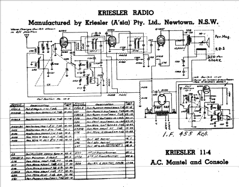
- Superhet allgemein; ZF/IF 455 kHz; Reflex
- Wellenbereiche
- Mittelwelle und Kurzwelle.
- Betriebsart / Volt
- Wechselstromspeisung / 220-240 Volt
- Lautsprecher
- Dynamischer LS, keine Erregerspule (permanentdynamisch)
- Material
- Bakelit (Pressstoff)
- von Radiomuseum.org
- Modell: Beehive 11-4U Ch= 11-4 - Kriesler Radio Company;
- Form
- Tischgerät ohne Drucktasten, bis 35 cm Breite (Kleingerät, meist dekorativ. Nur für Netzbetrieb, doch Transportgriff möglich).
- Bemerkung
-
Kriesler advertised this set & other post-war models as a "Sealed Radio". Solder joints were marked to prevent unauthorised servicing & tampering.
Walnut Bakelite cabinet. Also available in various colours for 1 Guinea (£1/1/-) extra. Price in WA for standard Walnut model, £19/8/6.
There are 36 variants of this model:
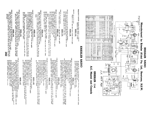
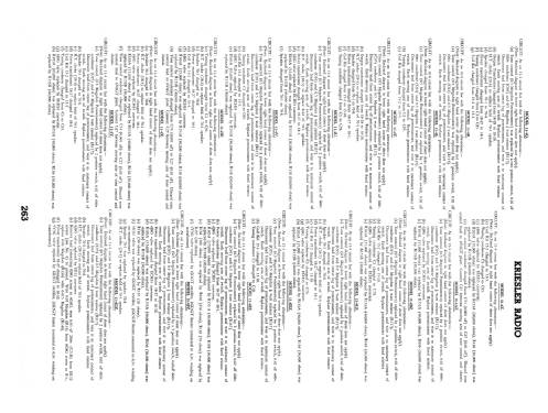
- CIRCUIT: As on 11-4 circuit but with the following alterations:- (Note: Enclosed diagram in lower right hand corner of sheet does not apply).
- Tone control (0.5 Megohm Potentiometer) was replaced by 2 position switch, 0.02 μF 600v. condenser (C94) and 0.5 Megohm ½ watt (R117). Disconnect lead from centre lug of potentiometer, and wire it to stationary contact of switch. Earth moving arm of switch. replace potentiometer with fixed resistor.
- H.T. Choke (28-3) to replace field of 70-1 speaker.
- Power transformer changed from 18-27 to 18-1.
- 6J8G valve replaced by ECH35 converter.
- R103A (15,000 Ω) was replaced by R153A (40,000 Ω), R136 (30,000 Ω) was replaced by R153B (40,000 Ω).
- Speaker changed from 70-1 to 70-8.
- COIL KIT: Part No. 15-2 (S.C. Tuning Condenser).
- DIAL GLASSES: Part No. 50-12 (Principle section). Part No. 50-25 (Rear glass).
- SPEAKER: Part No. 70-8 (5" Permanent magnet type).
- OUTPUT TRANSFORMER: Part No. 18-26.
- POWER TRANSFORMER: Part No. 18-1 (H.T.: 275v each side of centre tap).
PROCEDURE FOR REMOVING CHASSIS FROM CABINET:
- Remove knobs.
- Invert receiver.
- Remove base by breaking seal and unscrewing 4 x 3/16" screws in base of cabinet.
- Remove 4 x 3/16" nuts, situated in the inside corners of the chassis.
- Lay receiver on its back with spindles facing upwards.
- Place one hand each side the of chassis. With the forefingers, exert a downward pressure on the front panel, at the same time withdrawing the chassis from the cabinet.
CHASSIS NUMBERS:
Every receiver that leaves the Kriesler factory is given two chassis numbers.
The "Production" chassis number is stamped on a card. The card is riveted to the main chassis in such a location that the number is able to be read without removing the chassis from the cabinet. The "Production" chassis number is the number that should be quoted, together with the model number, when making enquiries.
The second chassis number (Prefix "0") is stamped into the metal chassis to provide a permanent record.
Both the abovementioned chassis numbers are recorded at the factory.
- Originalpreis
- 18.90 AUS £
- Literatur/Schema (1)
- - - Manufacturers Literature (Kriesler Technical Service Instructions.)
- Literatur/Schema (2)
- Australian Official Radio Service Manual AORSM (Volume 5, 1947, Page 188 & Volume 6, 1948, Page 262.)
- Autor
- Modellseite von Martin Kent angelegt. Siehe bei "Änderungsvorschlag" für weitere Mitarbeit.
- Weitere Modelle
-
Hier finden Sie 895 Modelle, davon 440 mit Bildern und 435 mit Schaltbildern.
Alle gelisteten Radios usw. von Kriesler Radio Company; Newtown (Sydney)