- País
- Italia
- Fabricante / Marca
- Magnadyne Radio; Torino
- Año
- 1936/1937
- Categoría
- Radio - o Sintonizador pasado WW2
- Radiomuseum.org ID
- 30590


Haga clic en la miniatura esquemática para solicitarlo como documento gratuito.
- Numero de valvulas
- 5
- Principio principal
- Superheterodino en general; ZF/IF 362.5 kHz
- Gama de ondas
- OM, OL y OC
- Tensión de funcionamiento
- Red: Corriente alterna (CA, Inglés = AC) / 110-230 Volt
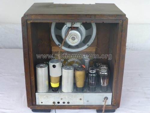
- Altavoz
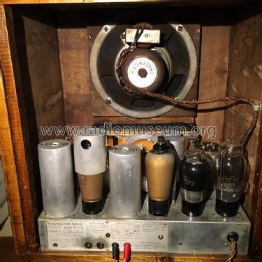
- Altavoz electrodinámico (bobina de campo) / Ø 20 cm = 7.9 inch
- Material
- Madera
- de Radiomuseum.org
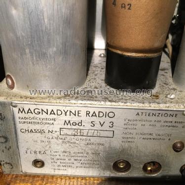
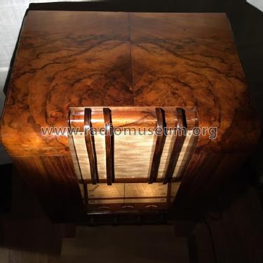
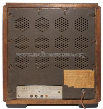
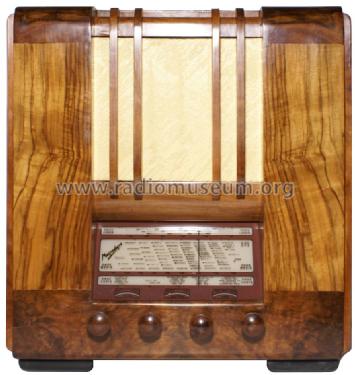
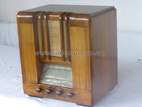
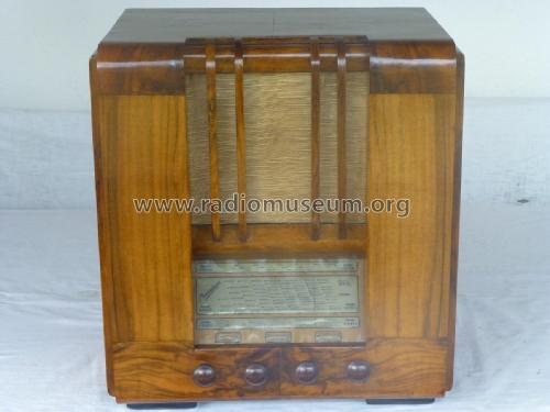
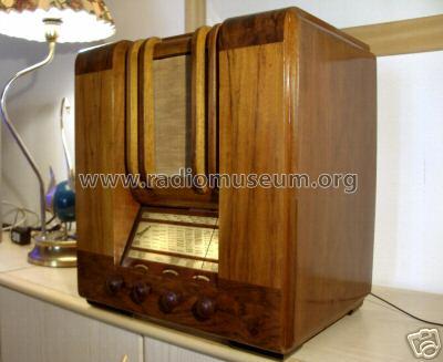
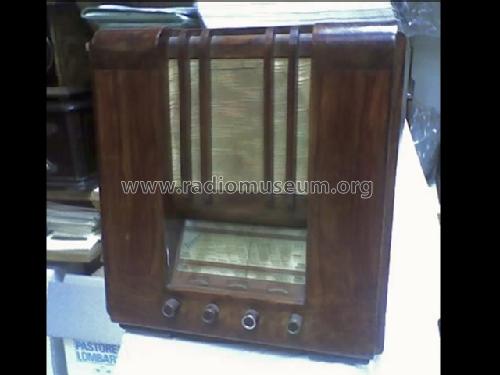
- Modelo: SV3 - Magnadyne Radio; Torino
- Forma
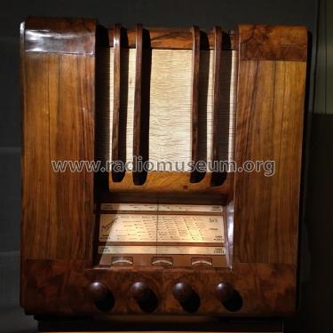
- Sobremesa alto de forma simple.
- Ancho, altura, profundidad
- 400 x 450 x 300 mm / 15.7 x 17.7 x 11.8 inch
- Anotaciones
- Variante circuitale del SV10. Controllo di selettività variabile.
Circuit variant of SV10.
- Documentación / Esquemas (1)
- Il Radio Libro (E.D. Ravalico) Edizioni Hoepli
- Autor
- Modelo creado por Alessandro De Poi. Ver en "Modificar Ficha" los participantes posteriores.
- Otros modelos
-
Donde encontrará 357 modelos, 276 con imágenes y 258 con esquemas.
Ir al listado general de Magnadyne Radio; Torino
Colecciones
El modelo es parte de las colecciones de los siguientes miembros.
Contribuciones en el Foro acerca de este modelo: Magnadyne Radio;: SV3
Hilos: 1 | Mensajes: 1
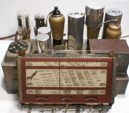
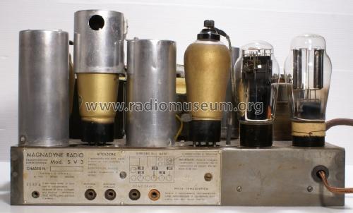
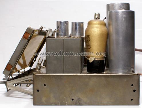
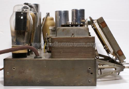
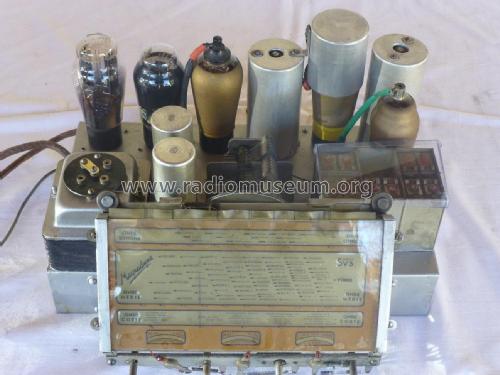
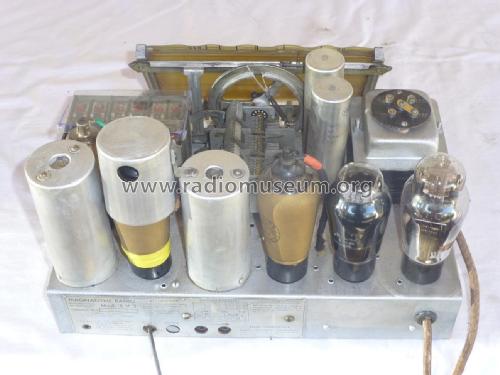
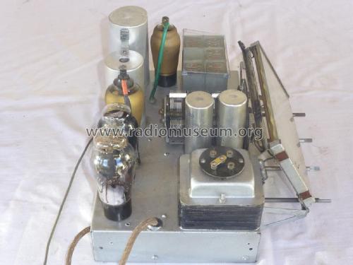
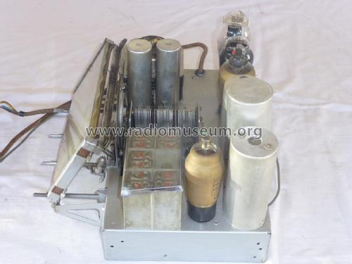
Magnadyne has been a creative and respected Italian producer of radio sets whose design philosophy in the 30s was focused on the audio quality of its products, often compared with musical instruments in advertising, and whose production strategy was based on the in-house realization of as many high-quality components as possible. This eventually led, in the 50s, even to the in-house development and production of non standard tubes used only in Magnadyne sets. Most models produced in the 30s rely on very similar circuits; in particular the RF section of most sets relies on the same LW-MW-SW scheme while the differences between different sets are based on the presence or absence of the variable selectivity control, on more or less sophisticated tone controls and on the output stage. Some of these sets relied on European tubes (typically AK1, AF2, E444, E443H, 1561) or on American ones like 6A7, 6D6, 75, 42 and 80; some sets, like the SV13, used a mix of European and American tubes (AK2, 78, 75, 42 and 80). The SV3 was an high end model based on the European set and was endowed with a variable selectivity control mechanically coupled with the tone control. The unit described in this note was almost untouched; the only substitutions concerned one electrolytic capacitor and the power cord. All other components were the original ones and also the tubes were original and characterized by the lead seal that testified the payment of Italian taxes; they were also perfectly efficient, with the exception of the E443H whose filament was interrupted. Because of the high quality of all components it was expected that only a very limited number of substitutions would have been necessary; this was, in fact, the case but some other aspects called for a substantial amount of work. This note describes the points that, according to my experience, require more attention. To shorten as much as possible the length of the note, these points will be treated as separate items of a list.
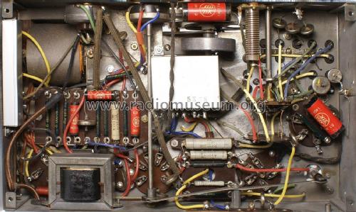
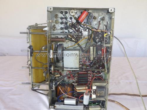
1) Restoring the wiring. Differently from many other receivers produced in the same years, most of the SV3 wiring was based on rubber–coated wires. Some wires were of the stranded type, others were solid and, to complete the picture, several colors were present for both types: gray, green, blue, red and yellow. Cloth covered wires were used only for the filaments of the tubes and for the connection of the chassis with the field coil and the output transformer. These were in perfect conditions while it has been necessary to substitute all rubber–coated ones. The most similar type of rubber–coated wires that it has been possible to find on the market are those produced by the German firm HEW-Kabel Heinz Eilentropp GmbH. Their extremely flexible silicon–rubber wires are available in several colors and diameters and can be purchased also from RS. Since it has not been possible to find rubber–coated rigid wires, these have been substituted with the cloth–coated wires available, in a large variety of colors, from Radio Daze.
2) Electrolytic capacitors. The pictures of this set show vertical tubular metallic electrolytic capacitors that look like present–day ones. One of the original capacitors (produced by Ducati) was still in place (and perfectly efficient too) and this allowed to observe that it was not connected to the chassis by means of a single large central nut as current ones but by means of two lateral 3MA screws. It is not difficult, starting from the metal casing of a vertical electrolytic capacitor, to reconstruct a basis of this type. The nominal values are 8 uF and the negative termination of the first capacitor must be insulated from the chassis because of the polarization circuit adopted in this set.
3) Mica capacitors. The mica capacitors used in the SV3 were produced by Ducati for very requiring applications and are contained in robust metal cases (see one of these capacitors in Figure 14). Their stability is excellent and most of them are still inside their nominal tolerance. In this set it has been necessary to compensate the variation of only one padding capacitor by adding a parallel silver mica capacitor in order to be able to align the scale at the lower frequencies.
4) Beware of circuit variations, they are not uncommon! Since the receiver needed an almost complete rewiring, it has been considered as prudential to compare the actual original circuit (the set had not been modified) with the available SV3 diagrams; this caution has been rewarding since an unknown variation of the original circuit has been found in the preamplifier stage. The initial circuit of the preamplifier and tone control of the SV3 is standard as can be seen in Figure 1.

Figure 1 – Preamplifier circuit, version 1
The more sophisticated alternative reported in Figure 2 was then adopted; here the load consists in the series connection of a 100Kohms resistor and of an inductance (with substantial air gap to avoid the possibility of saturation).

Figure 2 – Preamplifier circuit, version 2
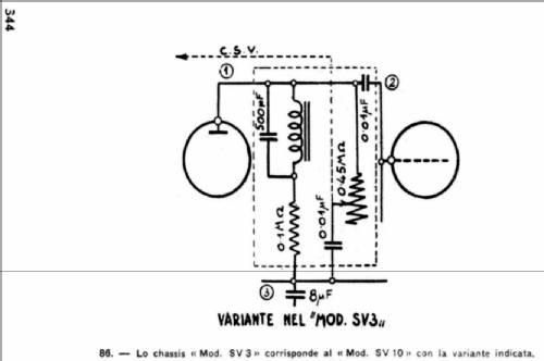
In the restored set a third, previously not documented variation was present; it is reported in Figure 3 that shows a definitely non standard tone control circuit (its potentiometer is also mechanically connected with the bandwidth control acting on the first I.F. transformer).
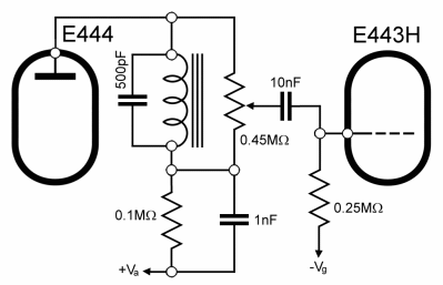
Figure 3 – Actual tone control circuit of the restored set
So, don’t take for granted the information that it is possible to deduce from the available diagrams, perform a check on the actual circuit implemented in your set if you want to preserve its integrity.
5) I.F. transformers. These beautiful transformers use a symmetrical scheme based on coils wrapped on a magnetic core and on a parallel air variable trimmer whose rotation is purposely mechanically limited (see Figure 4); in this way it acts as a fixed air capacitor with a parallel trim.
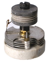
Figure 4 – I.F. transformer coil and parallel air capacitor/trim
In the first I.F. transformer the position of the primary winding (lower coil) is controlled by a leverage connected with the selectivity control as reported in Figure 5.

Figure 5 – Mechanical control of the distance between the windings in the first I.F. transformer
It is important to remember that the lever B is electrically connected to the chassis while the small piston A and the spring around it are connected to the plate of the AK1 i.e. to an high voltage. These parts are separated by the insulator C that must be accurately checked and properly lubricated.
6) Searching for the construction date. In many Italian receivers it is not uncommon to find the construction date on some components like, for instance, capacitor boxes. In this case the date that has been found is “21 NOV. 1936”. In other receivers the information can be more cryptic, like that shown in Figure 6, found on a Magnadyne S53.

Figure 6 – The date reported on this capacitor box is “31 OTT. Anno XIV”
In this case the problem is to decode the meaning of “Anno XIV” i.e. “Year 14”. This kind of indication was common in Italy under the Fascist government that intended to celebrate in this way his seizure of power; for all practical purposes it is sufficient to remember that year “I” extended from October 29, 1922 to October 28, 1923 and so on. The date above thus corresponds to October 31, 1935.
7) The unexpected box. The set contained a capacitor box that has not been observed in other Magnadyne receivers and that is not documented by the available diagrams of the SV3. It contained 4 high voltage 5 nF paper capacitors; two of them were used in a Y connection on the line while the others were connected across the high voltage secondary windings of the power transformer. The failure of some capacitors was evident (see Figure 7); fortunately, the box had been only disconnected but left in place.

Figure 7 – The capacitor box before and after restoring
This box offers an abundant space for the insertion of class Y high voltage capacitors.
8) Tuning mechanism. The axis of the tuning knob in many Magnadyne models of the 30s is endowed with a rubber sleeve that engages a cogwheel connected by means of a drive cord to the tuning capacitor. A coupling of this kind can be found also in some American radios of the same period; the rubber sleeve is usually no longer present or no longer operative. It can be substituted with 1 cm of the 6mm gasoline tube commonly used in cars (see Figure 8). Inserting the tube on the axis requires some disassembly. In these sets it is not infrequent to see the drive cord directly wrapped on the knob axis to avoid the necessity of substituting the rubber sleeve; this solution, however, bypasses a part of the tuning mechanism and leads to an excessive sensitivity to knob turning.

Figure 8 – Coupling of the tuning knob axis
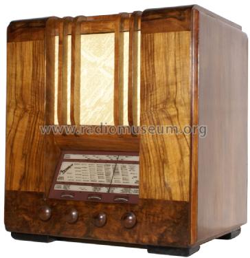
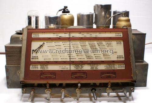
9) Dial glass. The original dial of the SV3 was printed on a celluloid sheet inserted between two glasses. On this set it had assumed the peculiar aspect that can be seen in Figure 9. It has been replaced with a version reprinted directly on a crystal with suitable thickness (Figure 10).

Figure 9 – The completely unreadable original dial glass of the SV3

Figure 10 – The reprinted dial glass
10) Alignment of the receiver. The alignment can be performed in the standard way; since a variable selectivity control (coupled with the tone control) is present, it is important to use the same setting of this control during the whole alignment procedure. The suggested setting is that corresponding to the maximal selectivity (complete counterclockwise rotation of the knob). The command of the trimmer of the (movable) primary winding of the first I.F. transformer could go unnoticed; it is indicated with a red arrow in Figure 5. The I.F. is 362.5 KHz.
No padding and input alignment trimmers are available for the short wave band. The padding and antenna alignment trimmers for the long and middle wave bands are denoted, in the partial diagram reported in Figure 11, with OL1, OL2, OM1, OM2, AL1, AL2, AM1 and AM2. The respective functions can be immediately deduced from the diagram.
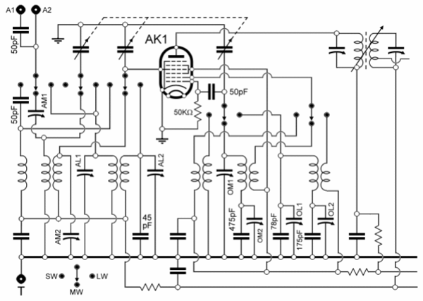
Figure 11 – Conversion stage of the Magnadyne SV3
All trimmers are contained in a box located in the upper right side of the chassis; it is important to note that the trimmers denoted as AM1 and AM2 are actually constituted by two parallel–connected trimmers indicated with AM1a, AM1b, AM2a and AM2b in Figure 12.

Figure 12 – Input and oscillator trimmers
11) Measure of the I.F. bandwidth. A measure of the frequency response of the I.F. channel is always recommended after the final alignment of a restored receiver. In this case I was also interested in measuring the effect of the selectivity control. The measure has been performed by means of the procedure reported in “Measuring the I.F. response in AM receivers”. The results associated with the selectivity control at the extreme points of its range are reported in Figure 13 that shows a well centered tuning in both cases and a very effective action of the selectivity control.

Figure 13 – Effect of the selectivity control on the bandwidth of the I.F. channel
12) Other considerations. The presence of a selectivity control and its mechanical connection with a very uncommon tone control circuit is a good example of the design philosophy of Magnadyne and of the attention of this producer to the quality of sound and to the ergonomics of the user interface. It can also be observed that the interaction between the tone control circuit and the selectivity control in the different positions of the knob can be modified by rotating the cam reproduced in Figure 14 with respect to the extension of the tone potentiometer axis.

Figure 14 – This cam controls the interaction between the tone control circuit and the selectivity control
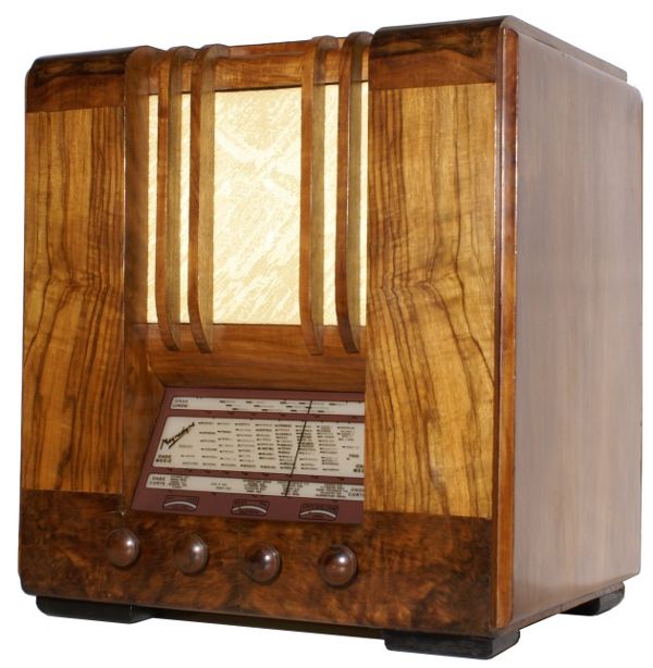
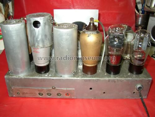
Figure 15 – The restored Magnadyne SV3
Roberto Guidorzi, 14.Apr.12