- Land
- USA
- Hersteller / Marke
- Montgomery Ward & Co. (Wards, Airline); Chicago, IL
- Jahr
- 1937
- Kategorie
- Rundfunkempfänger (Radio - oder Tuner nach WW2)
- Radiomuseum.org ID
- 48047
-
- Marke: Airline or Air-Line


Klicken Sie auf den Schaltplanausschnitt, um diesen kostenlos als Dokument anzufordern.
- Anzahl Röhren
- 6
- Hauptprinzip
- Superhet allgemein; ZF/IF 465 kHz; 3 NF-Stufe(n)
- Anzahl Kreise
- 6 Kreis(e) AM
- Wellenbereiche
- Mittelwelle und Kurzwelle.
- Betriebsart / Volt
- AKKU-Speisung (für alles, z.B. bei Autoradios und Amateurgeräten) / 6 Volt
- Lautsprecher
- Dynamischer LS, keine Erregerspule (permanentdynamisch) / Ø 6 inch = 15.2 cm
- Material
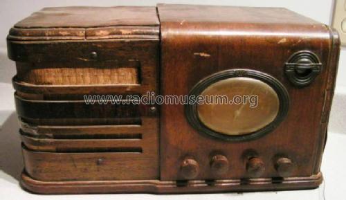
- Gerät mit Holzgehäuse
- von Radiomuseum.org
- Modell: 62-376 - Montgomery Ward & Co. Wards,
- Form
- Tischmodell, Zusatz nicht bekannt - allgemein.
- Bemerkung
- Push-pull audio amplifier. Built-in vibrator for B+
- Datenherkunft extern
- Ernst Erb
- Datenherkunft
- Collector's Guide to Antique Radios 4. Edition
- Schaltungsnachweis
- Rider's Perpetual, Volume 11 = ca. 1940 and before
- Literaturnachweis
- Rider's 11-14
- Weitere Modelle
-
Hier finden Sie 2333 Modelle, davon 1471 mit Bildern und 1829 mit Schaltbildern.
Alle gelisteten Radios usw. von Montgomery Ward & Co. (Wards, Airline); Chicago, IL
Forumsbeiträge zum Modell: Montgomery Ward & Co: 62-376
Threads: 1 | Posts: 3
I have done several simple radio restorations and have little knowledge about circuitry. I picked up the referenced 6 volt Monkey Wards circa 1936 farm radio radio recently and am completely stumped about the Rider schematic as shown. I have read a bit about the farm radios and how they use vibrators to simulate AC current so that a transformer can be used to adjust the voltage. I have also read a number of articles about building a battery eliminator to bypass the vibrator and power the radio. So here are my questions:
-1- The schematic doesn't give voltages on the tube pins, but I assume all the "A" heater voltage on the tubes is 6 volts; however when it comes to the "B" voltage I am lost. It appears that the oscillator and IF amp tubes use 90 volts, but can't figure out the other three tubes. I also see 135 and 145 volt power in places.
-2- Will it be possible to build a battery eliminator for this radio? If so I obviously need help so any suggestions will be appreciated.
-3- The other thing that confuses me is that I don't see a rectifier anywhere? Is this because the vibrator only creates a pseudo AC power that can be processed by the transformer but is still actually DC power?
Arnie Anderson, 05.Apr.15