- Produttore / Marca
- Montgomery Ward & Co. (Wards, Airline); Chicago, IL
- Anno
- 1937
- Categoria
- Radio (o sintonizzatore del dopoguerra WW2)
- Radiomuseum.org ID
- 48047
-
- Brand: Airline or Air-Line


Clicca sulla miniatura dello schema per richiederlo come documento gratuito.
- Numero di tubi
- 6
- Principio generale
- Supereterodina (in generale); ZF/IF 465 kHz; 3 Stadi BF
- N. di circuiti accordati
- 6 Circuiti Mod. Amp. (AM)
- Gamme d'onda
- Onde medie (OM) e corte (OC).
- Tensioni di funzionamento
- Batteria di accumulatori, per tutto (es. autoradio, radio amatoriali) / 6 Volt
- Altoparlante
- AP magnetodinamico (magnete permanente e bobina mobile) / Ø 6 inch = 15.2 cm
- Materiali
- Mobile in legno
- Radiomuseum.org
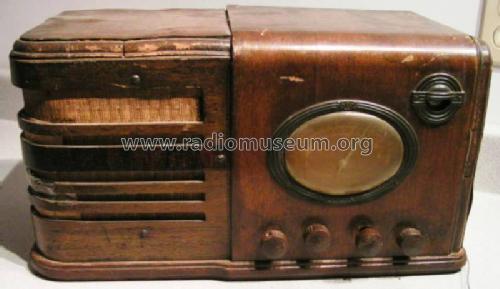
- Modello: 62-376 - Montgomery Ward & Co. Wards,
- Forma
- Soprammobile con qualsiasi forma (non saputo).
- Annotazioni
- Push-pull audio amplifier. Built-in vibrator for B+
- Fonte esterna dei dati
- Ernst Erb
- Fonte dei dati
- Collector's Guide to Antique Radios 4. Edition
- Riferimenti schemi
- Rider's Perpetual, Volume 11 = ca. 1940 and before
- Bibliografia
- Rider's 11-14
- Altri modelli
-
In questo link sono elencati 2308 modelli, di cui 1468 con immagini e 1805 con schemi.
Elenco delle radio e altri apparecchi della Montgomery Ward & Co. (Wards, Airline); Chicago, IL
Discussioni nel forum su questo modello: Montgomery Ward & Co: 62-376
Argomenti: 1 | Articoli: 3
I have done several simple radio restorations and have little knowledge about circuitry. I picked up the referenced 6 volt Monkey Wards circa 1936 farm radio radio recently and am completely stumped about the Rider schematic as shown. I have read a bit about the farm radios and how they use vibrators to simulate AC current so that a transformer can be used to adjust the voltage. I have also read a number of articles about building a battery eliminator to bypass the vibrator and power the radio. So here are my questions:
-1- The schematic doesn't give voltages on the tube pins, but I assume all the "A" heater voltage on the tubes is 6 volts; however when it comes to the "B" voltage I am lost. It appears that the oscillator and IF amp tubes use 90 volts, but can't figure out the other three tubes. I also see 135 and 145 volt power in places.
-2- Will it be possible to build a battery eliminator for this radio? If so I obviously need help so any suggestions will be appreciated.
-3- The other thing that confuses me is that I don't see a rectifier anywhere? Is this because the vibrator only creates a pseudo AC power that can be processed by the transformer but is still actually DC power?
Arnie Anderson, 05.Apr.15