12VF26R Ch= TS-23B (TV), HS-190A (radio)
Motorola Inc. (ex Galvin Mfg.Co. Chicago); Schaumburg (IL)
- Pays
- Etats-Unis
- Fabricant / Marque
- Motorola Inc. (ex Galvin Mfg.Co. Chicago); Schaumburg (IL)
- Année
- 1950
- Catégorie
- Récepteur de télévision avec radio ev. Enregistreur
- Radiomuseum.org ID
- 235186
Picture from Motorola Datasheet
Cliquez sur la vignette du schéma pour le demander en tant que document gratuit.
- No. de tubes
- 25
- Lampes / Tubes
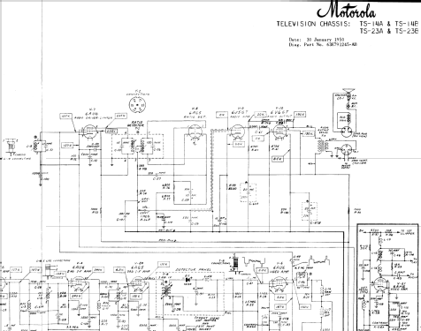
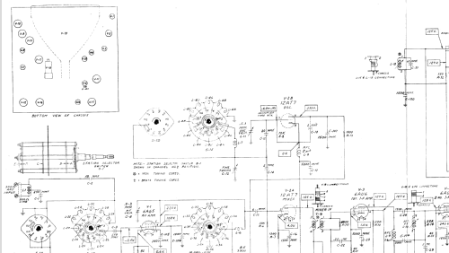
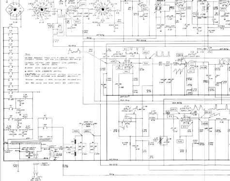
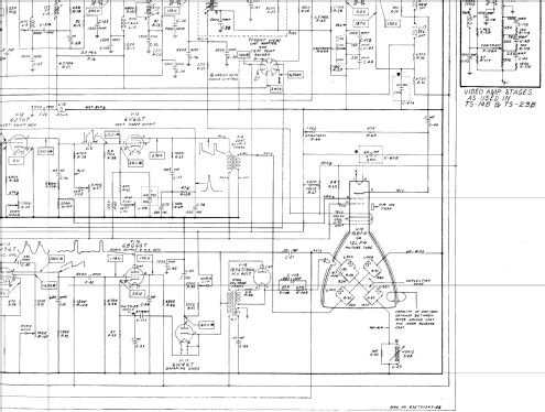
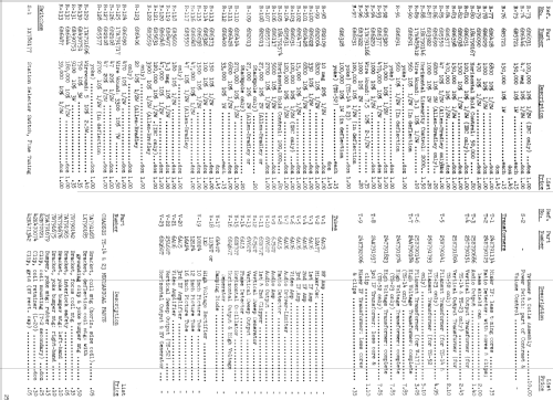
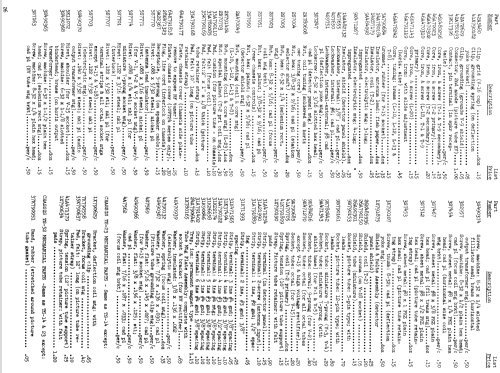
- 12BE6 12BA7 12BA6 12BA6 19T8 50C5 6AG5 12AT7 6AU6 6AU6 6AG5 6AH6 6AU6 6AL5 6J5GT 6V6GT 6SN7GT 6J5GT 6V6GT 6AL5 6SN7GT 6BQ6GT 6W4GT 1B3GT or 1X2 12LP4
- Principe général
- Super hétérodyne (en général); FI/IF 455/10700 kHz
- Gammes d'ondes
- PO et FM
- Particularités
- Tourne disque avec changeur
- Tension / type courant
- Alimentation Courant Alternatif (CA) / 60 cycles, 117 Volt
- Haut-parleur
- 2 HP
- Matière
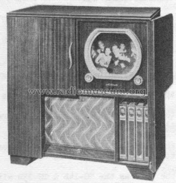
- Boitier en bois
- De Radiomuseum.org
- Modèle: 12VF26R Ch= TS-23B , HS-190A - Motorola Inc. ex Galvin Mfg.Co
- Forme
- Console avec pieds bas < 50% de la hauteur
- Remarques
-
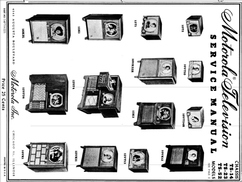
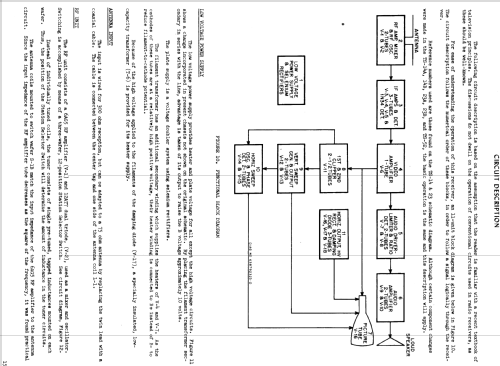
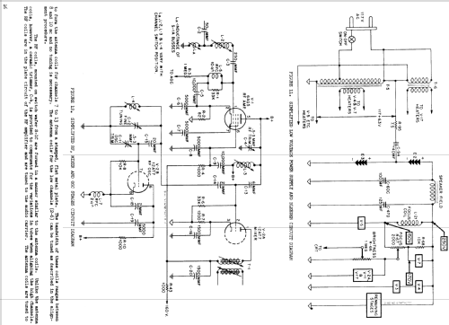
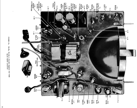
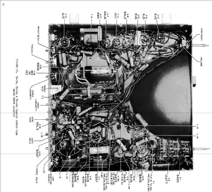
The Motorola 12VF26R is a combination BC/FM band receiver, phonograph and 12" b/w TV with US standard VHF Tuner channels 2 thru 13. Uses 19 tube TV chassis TS-23B and picture tube 12LP4. Also uses 6 tube radio chassis HS-190A and record changer M3RC. Except for common speaker, the TV and radio chassis operate independantly. Console model with Red Mahogany wooden cabinet. TV chassis has Qty(2) Selenium Rectifiers used for power supply rectification and Qty(1) germanium diode video detector. Radio chassis uses Qty(1) Selenium Rectifier. Has Qty(1) electrodynamic 10" speaker and Qty(1) electrodynamic 5" speaker, both with field coils.
This model is part of a series of TVs produced by Motorola using the TS-14, TS-23, and TS-52 chassis. According to Rider TV vol. 5, the TS-14 chassis was used in 10 inch sets with 10BP4 CRT. The TS-23 chassis was used in 12 inch sets with 12LP4 CRT, and is identical to the TS-14 chassis except for the high voltage transformer. The TS-52 chassis was used in 16 inch sets with 16AP4 CRT, and is similar to the TS-14 and TS-23 chassis, except for the high voltage transformer, addition of a second 6BQ6 horizontal output tube, and the use of 25L6GT for the vertical output tube.
There are variations for each chassis type: For TS-14A and TS-23A, the 3rd IF tube was changed from 6AU6 to 6AG5. For TS-14B and TS-23B, the video amplifier tube was changed from 6AU6 to 6AH6, and an additional tap was added to the contrast control. Chassis TS-52 has the same changes as TS-14B and TS-23B.
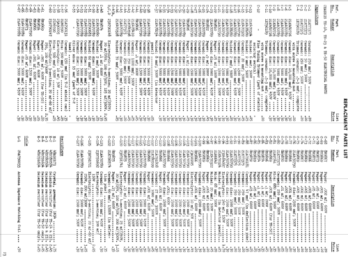
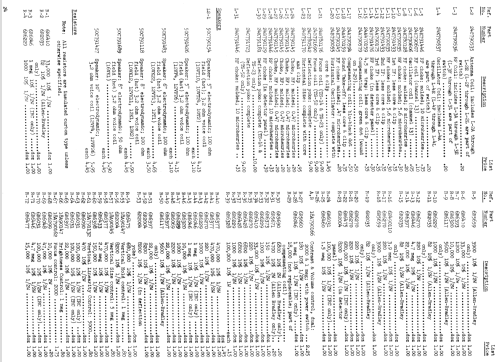
See table in document under "schematics" for more detailed explanation of differences between models (cabinet style, TV chassis, radio chassis, and record changer).
- Source du schéma
- Rider's Perpetual, Volume 21, Copyright 1950
- Schémathèque (1)
- Rider TV, vol. 5
- Schémathèque (2)
- - - Manufacturers Literature (Motorola Datasheet 54P7000225)
- Auteur
- Modèle crée par John Kusching. Voir les propositions de modification pour les contributeurs supplémentaires.
- D'autres Modèles
-
Vous pourrez trouver sous ce lien 4653 modèles d'appareils, 2980 avec des images et 4153 avec des schémas.
Tous les appareils de Motorola Inc. (ex Galvin Mfg.Co. Chicago); Schaumburg (IL)