12VF4R-C Ch= TS-23 (TV), HS-190 (radio)
Motorola Inc. (ex Galvin Mfg.Co. Chicago); Schaumburg (IL)
- País
- Estados Unidos
- Fabricante / Marca
- Motorola Inc. (ex Galvin Mfg.Co. Chicago); Schaumburg (IL)
- Año
- 1950
- Categoría
- Televisión con radio y/o grabadora.
- Radiomuseum.org ID
- 105641
Source: Rider TV, vol. 5
Picture from Motorola Datasheet
Haga clic en la miniatura esquemática para solicitarlo como documento gratuito.
- Numero de valvulas
- 25
- Válvulas
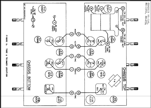
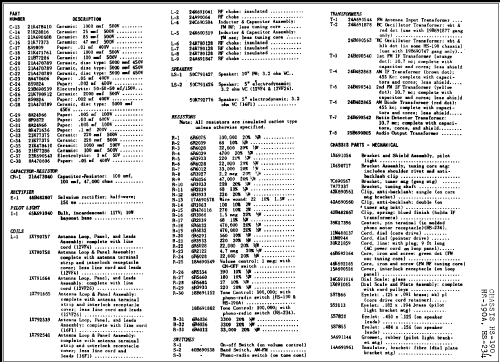
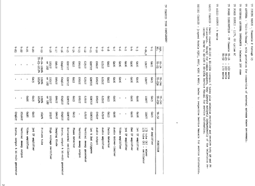
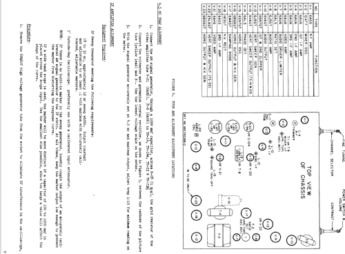
- 12BE6 12BA7 12BA6 12BA6 19T8 50C5 6AG5 12AT7 6AU6 6AU6 6AU6 6AU6 6AU6 6AL5 6J5GT 6V6GT 6SN7GT 6J5GT 6V6GT 6AL5 6SN7GT 6BQ6GT 6W4GT 1B3GT or 1X2 12LP4
- Principio principal
- Superheterodino en general; ZF/IF 455/10700 kHz
- Gama de ondas
- OM y FM
- Especialidades
- Tocadiscos con cambiador autom.
- Tensión de funcionamiento
- Red: Corriente alterna (CA, Inglés = AC) / 60 cycles, 117 Volt
- Altavoz
- 2 Altavoces
- Potencia de salida
- 4 W (undistorted)
- Material
- Madera
- de Radiomuseum.org
- Modelo: 12VF4R-C Ch= TS-23 , HS-190 - Motorola Inc. ex Galvin Mfg.Co
- Forma
- Consola en general
- Anotaciones
-
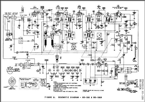
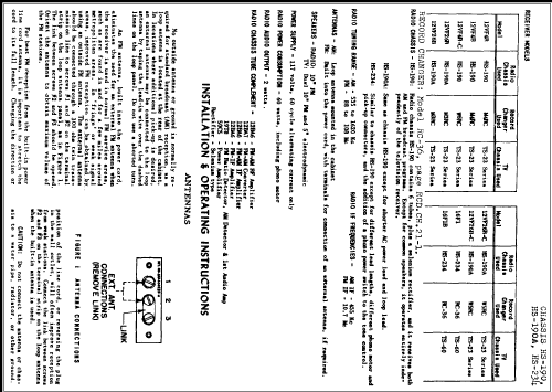
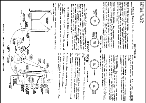
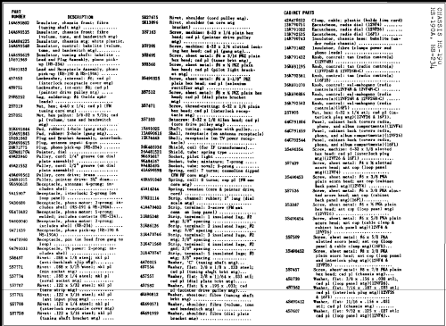
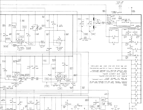
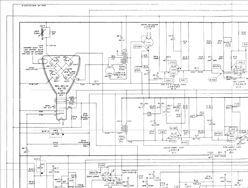
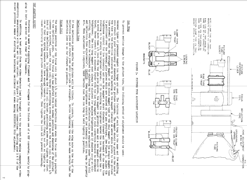
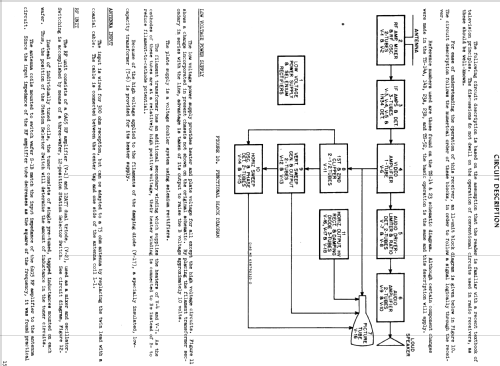
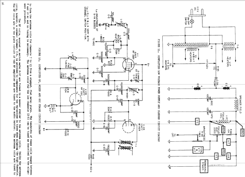
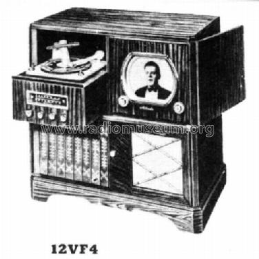
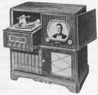
The Motorola 12VF4R-C is a combination BC/FM band receiver, phonograph and 12" b/w TV with US standard VHF Tuner channels 2 thru 13. Uses 19 tube TV chassis TS-23 and picture tube 12LP4. Also uses 6 tube radio chassis HS-190 and record changer W6RC. Except for common speaker, the TV and radio chassis operate independantly. Console model with Red Mahogany wooden cabinet. TV chassis has Qty(2) Selenium Rectifiers used for power supply rectification and Qty(1) germanium diode video detector. Radio chassis uses Qty(1) Selenium Rectifier. Has Qty(1) electrodynamic 10" speaker and Qty(1) electrodynamic 5" speaker, both with field coils.
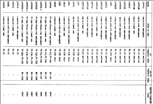
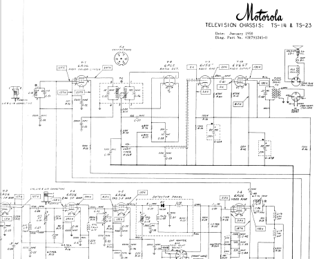
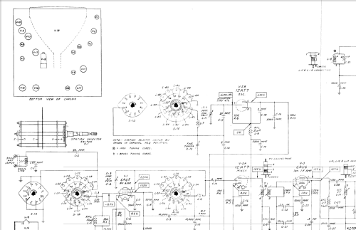
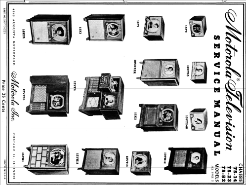
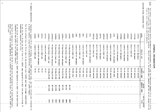
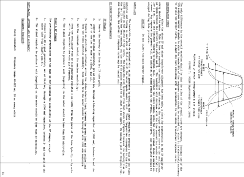
This model is part of a series of TVs produced by Motorola using the TS-14, TS-23, and TS-52 chassis. According to Rider TV vol. 5, the TS-14 chassis was used in 10 inch sets with 10BP4 CRT. The TS-23 chassis was used in 12 inch sets with 12LP4 CRT, and is identical to the TS-14 chassis except for the high voltage transformer. The TS-52 chassis was used in 16 inch sets with 16AP4 CRT, and is similar to the TS-14 and TS-23 chassis, except for the high voltage transformer, addition of a second 6BQ6 horizontal output tube, and the use of 25L6GT for the vertical output tube.
There are variations for each chassis type: For TS-14A and TS-23A, the 3rd IF tube was changed from 6AU6 to 6AG5. For TS-14B and TS-23B, the video amplifier tube was changed from 6AU6 to 6AH6, and an additional tap was added to the contrast control. Chassis TS-52 has the same changes as TS-14B and TS-23B.
See table in document under "schematics" for more detailed explanation of differences between models (cabinet style, TV chassis, radio chassis, and record changer).
- Referencia esquema
- Rider's Perpetual, Volume 21, Copyright 1950
- Documentación / Esquemas (1)
- Rider TV, vol. 5
- Documentación / Esquemas (2)
- - - Manufacturers Literature (Motorola Datasheet 54P7000225)
- Autor
- Modelo creado por Egon Penker. Ver en "Modificar Ficha" los participantes posteriores.
- Otros modelos
-
Donde encontrará 4655 modelos, 2982 con imágenes y 4153 con esquemas.
Ir al listado general de Motorola Inc. (ex Galvin Mfg.Co. Chicago); Schaumburg (IL)