Ultradyne L2 UV tubes
Phenix Radio Corp.; New York
- Produttore / Marca
- Phenix Radio Corp.; New York
- Anno
- 1924/1925
- Categoria
- Radio (o sintonizzatore del dopoguerra WW2)
- Radiomuseum.org ID
- 50438
-
- alternative name: Lacault, R.E.


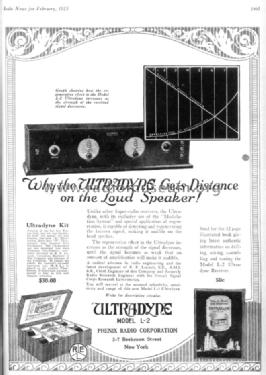
Radio News, Feb.1925, p.1463

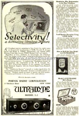
Radio Broadcast, Nov. 1924, p. 111
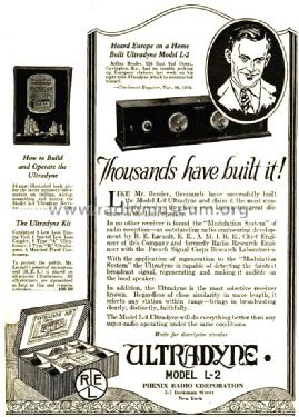
Radio Broadcast, Nov. 1924, p. 303

Radio Broadcast, Mar. 1925, p. 943
Radio Broadcast, Apr. 1925, p. 1129

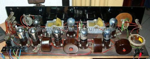
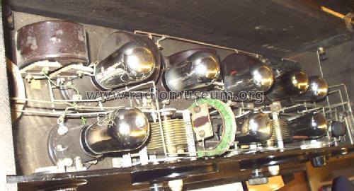
RLE Phenix Ultradyne L2 Kit.


From the right end

From the left end
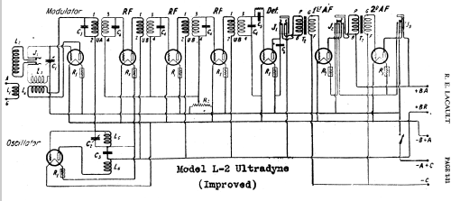
Clicca sulla miniatura dello schema per richiederlo come documento gratuito.
- Numero di tubi
- 8
- Principio generale
- Supereterodina (in generale); ZF/IF 115 kHz
- N. di circuiti accordati
- 7 Circuiti Mod. Amp. (AM)
- Gamme d'onda
- Solo onde medie (OM).
- Tensioni di funzionamento
- Batterie (di accumulatori e/o a secco)
- Altoparlante
- - Questo apparecchio richiede altoparlante/i esterno/i.
- Materiali
- Mobile in legno
- Radiomuseum.org
- Modello: Ultradyne L2 [UV tubes] - Phenix Radio Corp.; New York
- Forma
- Soprammobile a cassapanca o cassetta, solitamente con coperchio (NON a leggio)
- Dimensioni (LxAxP)
- 32 x 9 x 10 inch / 813 x 229 x 254 mm
- Annotazioni
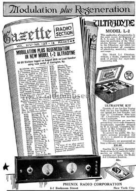
- The Ultradyne L2 was first manufactured for the UV201A with thoriated filament, which was announced in December 1922. In August 1925 the UV201A was withdrawn and replaced by the UX201A. They have later also been fitted with UX112, UX171 or UX171A but we don't put that into the tube line up as "or" because that was at least a year later of the UX201A variant.
The Ultradyne L2 is a super with RF reaction. Whether it is similar to the Keystone L2's is uncertain. The manufacturer Keystone Radio Service offered kits according to The Radio Trade Directory of Aug.,1925.
Two dials (primary tuning control knobs).
Siehe auch Triodensuperhets.
- Fonte esterna dei dati
- Ernst Erb
- Fonte dei dati
- Radio Collector`s Guide 1921-1932
- Riferimenti schemi
- Rider's Perpetual, Volume 1 = 1931/1934 (for 1919-1931)
- Letteratura / Schemi (1)
- Rider's Perpetual, Volume 1 = 1931/1934 (1919 to 1931) (see misc. 1-11 Lacault)
- Letteratura / Schemi (2)
- Radio Broadcast, Nov. 1924, p. 111
- Altri modelli
-
In questo link sono elencati 15 modelli, di cui 9 con immagini e 5 con schemi.
Elenco delle radio e altri apparecchi della Phenix Radio Corp.; New York
Collezioni
Il modello Ultradyne fa parte delle collezioni dei seguenti membri.
Discussioni nel forum su questo modello: Phenix Radio Corp.;: Ultradyne L2
Argomenti: 1 | Articoli: 1
Die Besonderheit der Ultradyne-Schaltung liegt darin, dass die Mischtriode keine Anodengleichspannung erhält. Stattdessen liegt sie an der Oszillatorwechselspannung. und wird damit voll durchgesteuert.
Die Anodenspannung für die Mischtriode kommt galvanisch über mehrere Spulen (1.ZF-Filter und Eingangskreis-Rückkopplung) vom Gitter der Oszillatorröhre. Am Gitter der Oszillatorröhre steht die Schwingung leicht ins negative verschoben, mit 50 V positiver und 60 V negativer Halbwelle. Entsprechend an der Mischeranode (Oszillogramm ohne Eingangssignal, bei verstimmtem Eingangskreis).
20V/div. 
Konrad Birkner † 12.08.2014, 02.Sep.11