16B 16/16A-121 Version 2
Philco, Philadelphia Stg. Batt. Co.; USA
- Country
- United States of America (USA)
- Manufacturer / Brand
- Philco, Philadelphia Stg. Batt. Co.; USA
- Year
- 1934
- Category
- Broadcast Receiver - or past WW2 Tuner
- Radiomuseum.org ID
- 118867


Click on the schematic thumbnail to request the schematic as a free document.
- Number of Tubes
- 11
- Main principle
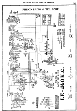
- Superheterodyne (common); ZF/IF 460 kHz
- Wave bands
- Broadcast plus more than 2 Short Wave bands.
- Power type and voltage
- Alternating Current supply (AC) / 115 Volt
- Loudspeaker
- Electro Magnetic Dynamic LS (moving-coil with field excitation coil) / Ø 10 inch = 25.4 cm
- Power out
- 10 W (unknown quality)
- Material
- Wooden case
- from Radiomuseum.org
- Model: 16B 16/16A-121 [Version 2] - Philco, Philadelphia Stg. Batt
- Shape
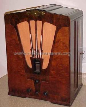
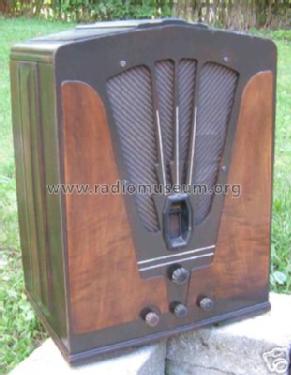
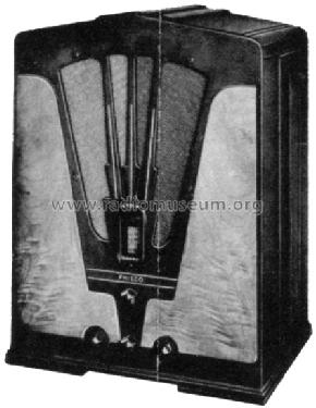
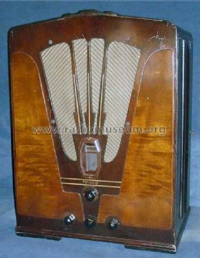
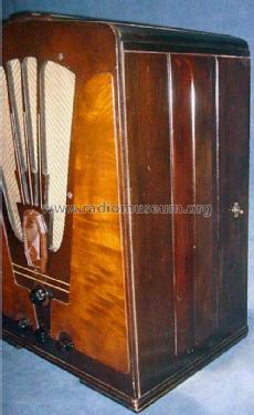
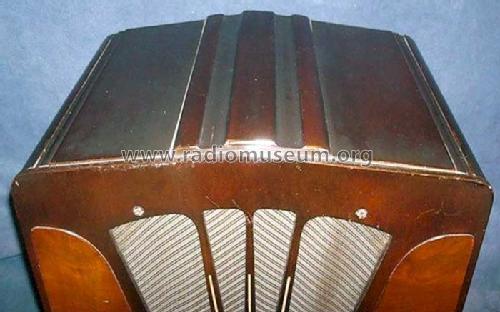
- Tablemodel, Tombstone = decorative upright, not cathedral but can have rounded edges.
- Dimensions (WHD)
- 16.5 x 21 x 11 inch / 419 x 533 x 279 mm
- Notes
-
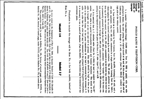
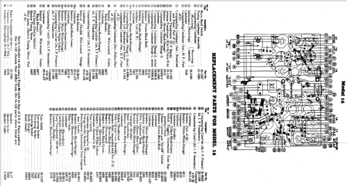
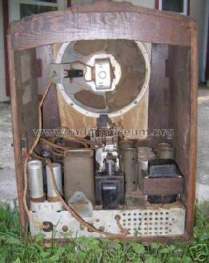
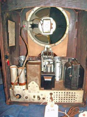
The 2nd version of the Philco 16B was introduced in June, 1934. The cabinet has a shallow peaked top with 3 narrow bars running from the front of the cabinet to the back along the peak. It uses the code 121 early chassis.
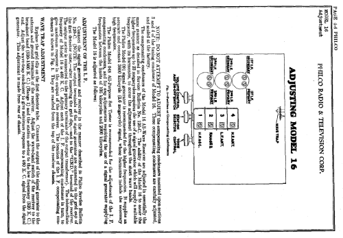
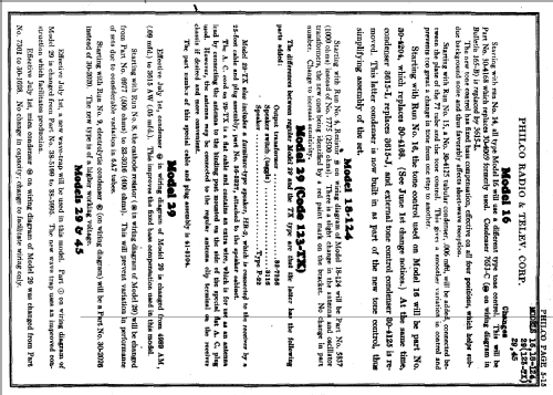
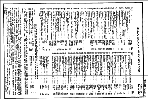
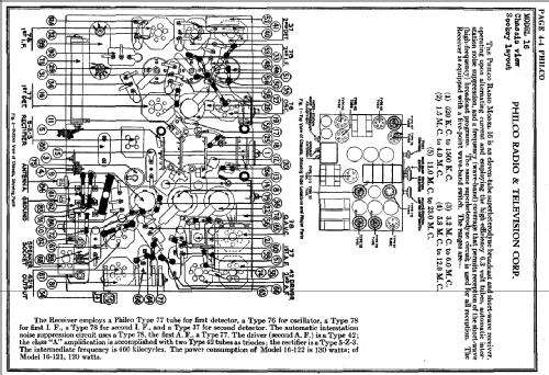
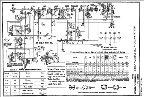
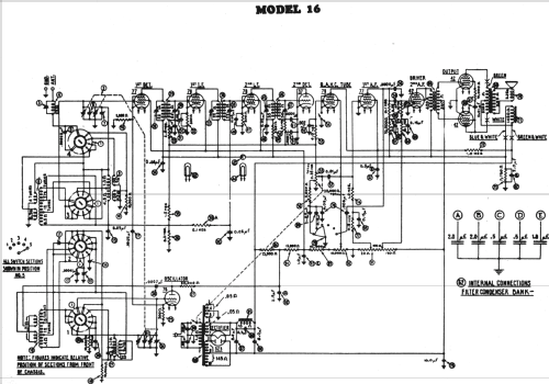
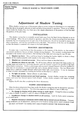
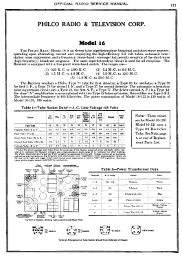
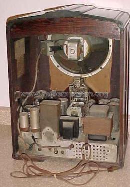
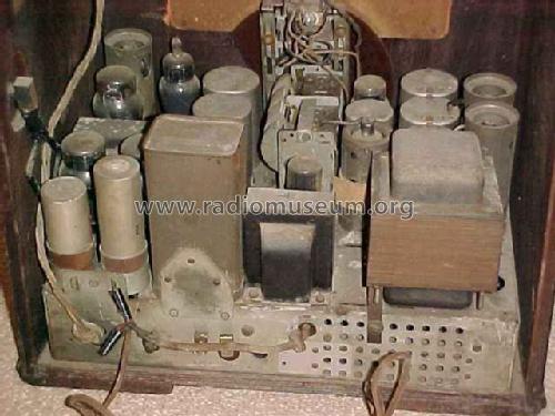
The model 16 series were high-end multi-band 11-tube radios sold by Philco for about 2 years spanning the 1933, 1934, and 1935 model years. There were two basic versions of the chassis referred to as 'early' and 'late'. Both the early and late chassis used a type 80 rectifier tube for the 16B table models, and a 5Z3 rectifier for the console models. Both chassis included dual IF-amp stages and a shadow meter (tuning aid). Both chassis were available in a version for 25-40 Hz power, and these chassis are marked as "16A" (where the -A suffix is a chassis suffix, not to be confused with the cabinet suffix on the main model number).
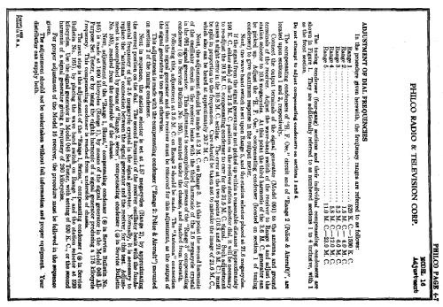
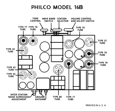
The early chassis used in 1933-34 included a QAVC ("quiet automatic volume control") squelch circuit to silence noise between stations. Squelch was implemented with a dedicated type 78 tube, and controlled with an on/off switch on the side and a potentiometer on the back to adjust the squelch level. The early chassis received five bands: 520-1500 kHz, 1.5-4.0 MHz, 3.2-6.0 MHz, 5.8-12.0 MHz and 11.0-23.0 MHz.
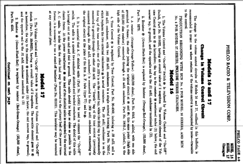
The late chassis (1934-35) eliminated the QAVC feature and repurposed its 78 tube to be an RF amplifier stage in the front end, thus maintaining the 11-tube count. The switch on the side of the cabinet was used as a bass-boost control called "Loudness". The late chassis covered a similar tuning range, but with only four bands: 550-1500 KHz, 1.5-4.1 MHz, 4.1-10.0 MHz, and 10.0-22.5 MHz.
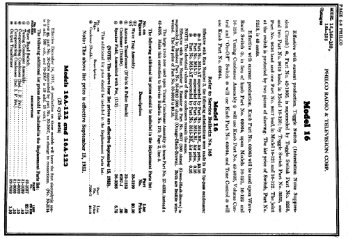
The chassis codes are as follows:
Code 121: early chassis with 80
Code 122: early chassis with 5Z3
Code 123: unknown
Code 125: late chassis with 80
Code 126: late chassis with 5Z3
Code 127: unknown
There were fifteen versions of model 16 in different cabinet styles over the three-model-year span:
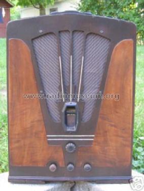
Four versions of the 16B cathedral/tombstone,
Three versions of the 16L lowboy console,
Four versions of the 16X floor-type console,
Three versions of the 16RX chairside,
A special 16CPX chairside.
- Net weight (2.2 lb = 1 kg)
- 19 kg / 41 lb 13.6 oz (41.85 lb)
- Price in first year of sale
- 90.00 $
- Source of data
- Philco Radio 1928-1942
- Circuit diagram reference
- Rider's Perpetual, Volume 4 = ca. 1934 and before
- Mentioned in
- Collector's Guide to Antique Radios (6th edition)
- Literature/Schematics (1)
- Machine Age to Jet Age II (Philco 1928-36 Wiring Diagrams, Parts Lists, and Essential Service Data)
- Author
- Model page created by Konrad Birkner † 12.08.2014. See "Data change" for further contributors.
- Other Models
-
Here you find 4120 models, 2227 with images and 3768 with schematics for wireless sets etc. In French: TSF for Télégraphie sans fil.
All listed radios etc. from Philco, Philadelphia Stg. Batt. Co.; USA