- Country
- United States of America (USA)
- Manufacturer / Brand
- Philco, Philadelphia Stg. Batt. Co.; USA
- Year
- 1932/1933
- Category
- Broadcast Receiver - or past WW2 Tuner
- Radiomuseum.org ID
- 51169


Click on the schematic thumbnail to request the schematic as a free document.
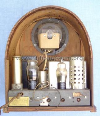
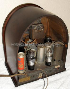
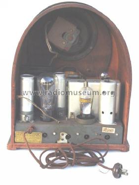
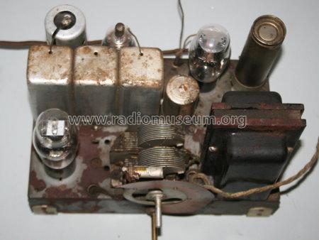
- Number of Tubes
- 4
- Main principle
- Superheterodyne (common); ZF/IF 450 kHz; 1 AF stage(s)
- Tuned circuits
- 3 AM circuit(s)
- Wave bands
- Broadcast only (MW).
- Power type and voltage
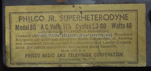
- Alternating Current supply (AC) / 115 Volt
- Loudspeaker
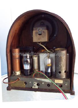
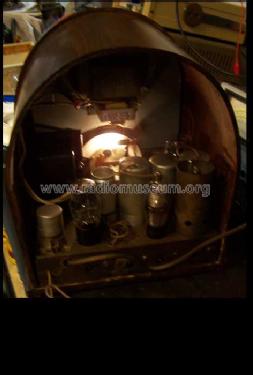
- Electro Magnetic Dynamic LS (moving-coil with field excitation coil)
- Material
- Wooden case
- from Radiomuseum.org
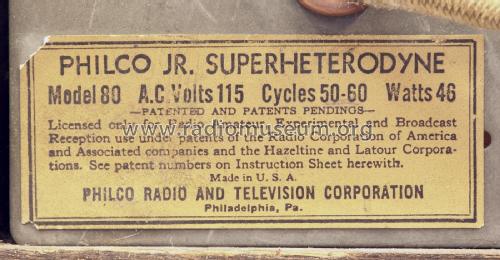
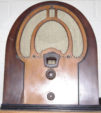
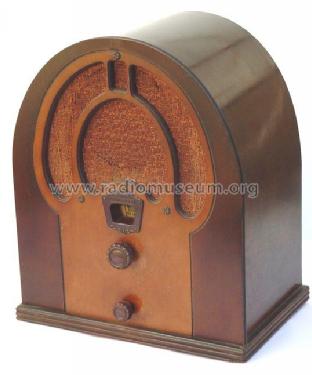
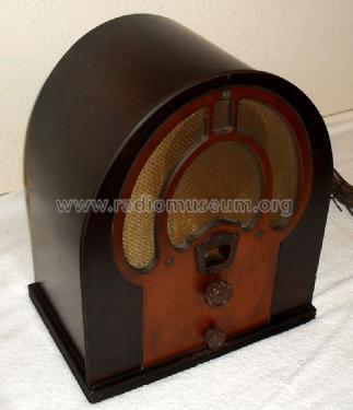
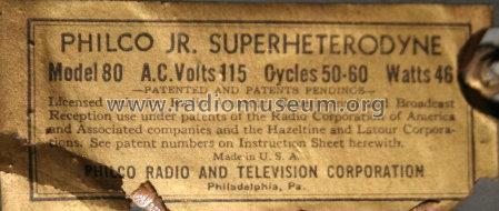
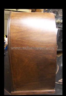
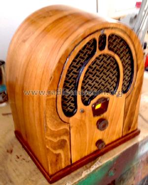
- Model: 80B - Philco, Philadelphia Stg. Batt
- Shape
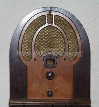
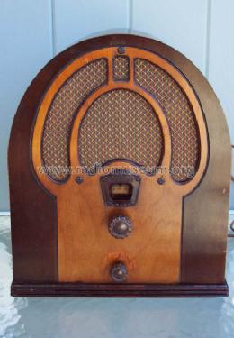
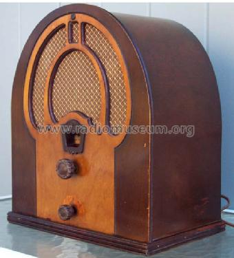
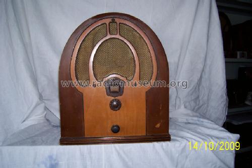
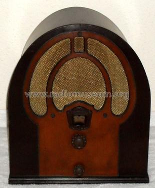
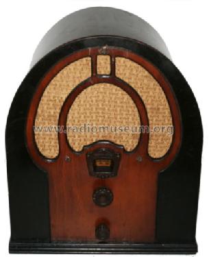
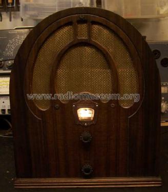
- Table-Cathedral-Type (upright, round top or gothic arch, not rounded edges only).
- Dimensions (WHD)
- 300 x 335 x 210 mm / 11.8 x 13.2 x 8.3 inch
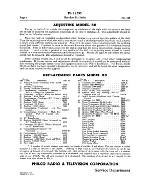
- Notes
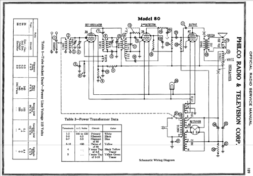
- The 80 series models were referred to as "Philco Junior" and were inexpensive entry-level radios employing a superheterodyne circuit with a regenerative stage to increase gain in the absence of an IF amplifier stage. Model 80B is a cathedral (with low-cost flat front), 80C is a compact rectangular wooden tabletop model, 80P is a plug-in "portable," and there is also an 80 Colonial clock.
- Net weight (2.2 lb = 1 kg)
- 6.5 kg / 14 lb 5.1 oz (14.317 lb)
- Price in first year of sale
- 18.00 $
- External source of data
- Ernst Erb
- Source of data
- Radio Collector`s Guide 1921-1932
- Circuit diagram reference
- Rider's Perpetual, Volume 3 = 1933 and before
- Mentioned in
- Collector's Guide to Antique Radios 4. Edition
- Literature/Schematics (1)
- Philco Radio 1928-1942 (Philco 1928-36 Wiring Diagrams, Parts Lists, and Essential Service Data)
- Other Models
-
Here you find 4120 models, 2227 with images and 3768 with schematics for wireless sets etc. In French: TSF for Télégraphie sans fil.
All listed radios etc. from Philco, Philadelphia Stg. Batt. Co.; USA
Collections
The model 80B is part of the collections of the following members.
- Richard Adams (USA)
- Mike Argetsinger (USA)
- Jürgen Bauch (D)
- Walter Brendecke (USA)
- Gualtiero Cainelli (I)
- Domenec Cots-Baraldés (E)
- Rudolph D'Amato (USA)
- Alan Scott Douglas † 16.11.15 (USA)
- Bob Elbert (USA)
- Jose-Antonio Exposito-Arjona (E)
- Manuel Garnelo (E)
- Francisco Martins (P)
- Charles Maulding (USA)
- Roberto Montalto (I)
- Glen Orriss (AUS)
- Thomas Ranz (USA)
- Salvador Saura-Lopez (E)
- Michael Schaub (USA)
- Wilhelm Siepe (D)
- Gidi Verheijen (NL)
Forum contributions about this model: Philco, Philadelphia: 80B
Threads: 1 | Posts: 2
Fellow Radiophiles,
I own a Philco 80B Junior in the cathedral case with the simple flat front.
This radio only had two simple problems. One was sudden changes in the level of regeneration, and the other was too much detector distortion.
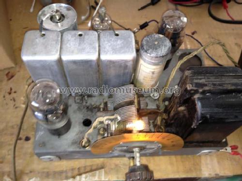
The sudden changes in regeneration were caused by dirty chassis ground connections at the screws that hold the molded bakelite single and double capacitor units. The application of DeOxit contact cleaner from CAIG laboratories to the screws, while loosening and tightening them, eliminated the unstable regeneration problem. As a preventive measure, I also touched up with DeOxit every grounded riveted at the tube sockets, along with the socket contacts, and any other contact I found, including the sliding contacts of the dual gang tuning capacitor. The operation is now very reliable.
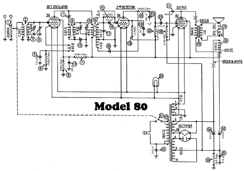
The remaining problem was the excessive distortion at the detector grid. This radio has only one stage of gain provided by the type 36 tetrode used as a self-oscillating superheterodyne frequency converter, before the detector grid of the second type 36 tetrode working as a regenerative grid-leak detector.
Under these conditions, the signal level presented to the grid, is often not larger than the built-in contact potential around -0.7V that appears at the grid that is caused by the space charge surrounding the cathode. Contrast this situration with the signal levels presented to the diode detector of a conventional superhet radio that has a separate IF gain stage, where the IF signal present to the detector diode is at least 0.5Vp-p. When there is a large signal, the detector operation is very linear because the relatvely large p-p amplitude makes the detector diode appear fully on or fully off during signal rectification.
At the usual small signal levels found at the input of regenerative detectors, the detection operation is quite non-linear for the small signal region under 100mV, and may become even worse for signals that operate partly in the small signal and large signal regions. All this just makes the DC bias point of the grid all the more critical to achieve reasonably low distortion over a wide operating range. One way to find the cleanest bias voltage is to experiment with different bias levels for a particular tube. These conditions change with tube age, as the negative contact potential that appears at the grid drops with reduced emission.
The following schematic shows the result of my experimentation with the bias level at the grid of regenerative grid leak detector in my Philco Junior 80B.
A 20Meg resistor made of two 10Meg resistors wired in series to the -16V grid bias source for the output tube, and soldered directly to the grid cap, provided distortion free operation for strong and weak signals. Keep in mind the signal strength is set by the volume control in the antenna circuit, so that the signal strenght presented to the detection grid is always the same for a given output volume.
The new old stock type 36 tube in the detector stage presented the following contact potential voltages under different load conditions, as measured with a Fluke 87III voltmeter with 10Meg input resistance in series with a 10Meg isolation resistor:
 -960mV with the 20Meg meter load and with the grid cap removed
-820mV when a 1Meg resistor was added, thus suggesting a grid inpedance around 160k at this voltage
-900mV when the 4Meg grid leak was reconnected with the grid cap, and the mid point of the two 10Meg grid leak resistors was grounded to kill the -16V bias source. This gives a total 2.5Meg load.
-1160mV with the 4Meg grid leak in place and the 20Meg bias to -16V. Calculating out the effect the 20Meg meter load, we get -1353mV, but that is assuming infinite grid impedance. The actual voltage should be somewhere between -1160mV and -1353mV
This final voltage is the current bias level at the grid. It was arrived at by listening for the least distortion and also by observing the least distortion of the audio signal driving the output stage. This point also gives the loudest volume and detection sensitivity, and the regeneration is not affected by signal amplitude.
The -1.2V bias is probably very near the unloaded contact potential voltage. Perhaps a slightly lower voltage might have worked better for very weak signals, but I was very satisfied with the operation I got from strong and weak stations.
A positive external bias source that forced the grid into a lower impedance region also gave very low distortion levels, but with greatly reduced volume.
A related thread dealing with the values of capacitance used in the grid leak circuit may be of interest too.
Regards,
-Joe
Joe Sousa, 11.Jul.10