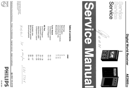
AE-3905
Philips - Österreich
- Country
- Austria
- Manufacturer / Brand
- Philips - Österreich
- Year
- 1988 ??
- Category
- Broadcast Receiver - or past WW2 Tuner
- Radiomuseum.org ID
- 75912


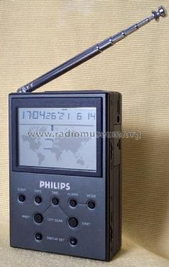


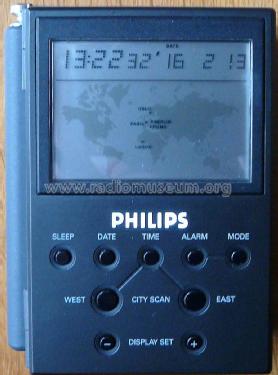
Façade horloge
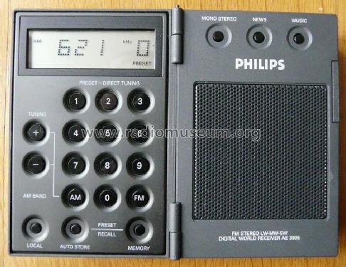
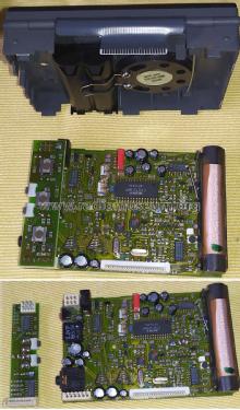
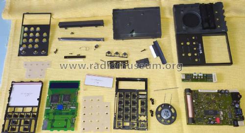
Appareil ouvert
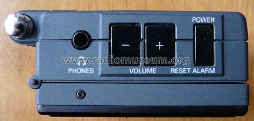
dessus
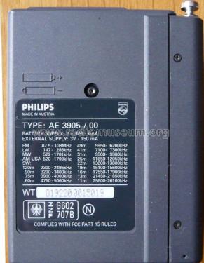
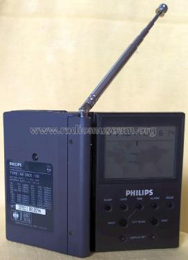
arrière

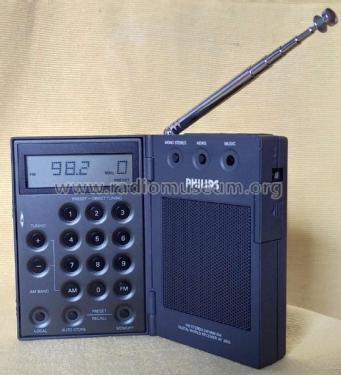
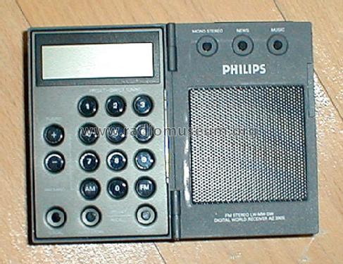
Ouvert,sur FM
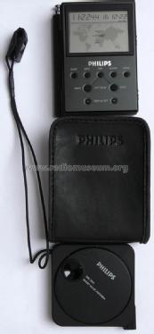
AE905 pouch SW antenna
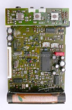
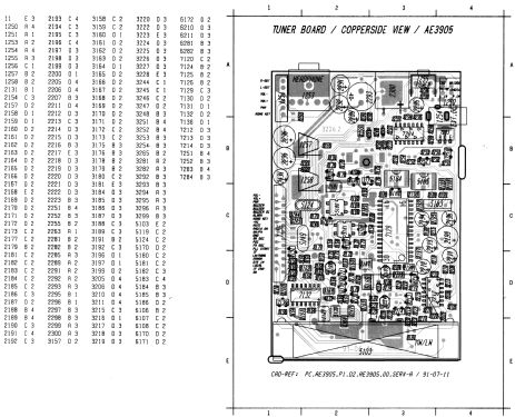
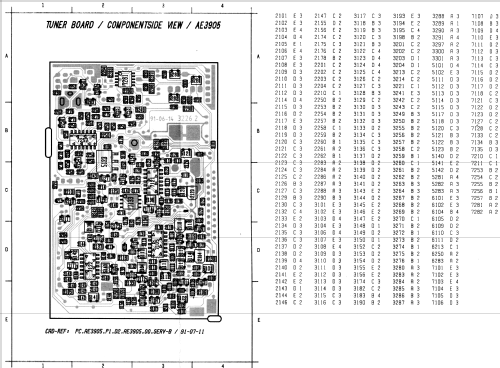
circuit imprimé
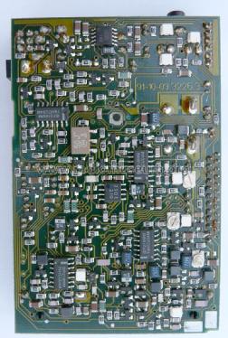
envers du CI


Click on the schematic thumbnail to request the schematic as a free document.
- Number of Transistors
- Semiconductors present.
- Semiconductors
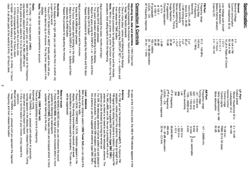
- Main principle
- Superhet, double/triple conversion
- Wave bands
- Broadcast, Long Wave, Short Wave plus FM or UHF.
- Power type and voltage
- Batteries / addl. power jack / 2 x 1,5 / 3 Volt
- Loudspeaker
- Permanent Magnet Dynamic (PDyn) Loudspeaker (moving coil) / Ø 4 cm = 1.6 inch
- Material
- Plastics (no bakelite or catalin)
- from Radiomuseum.org
- Model: AE-3905 - Philips - Österreich
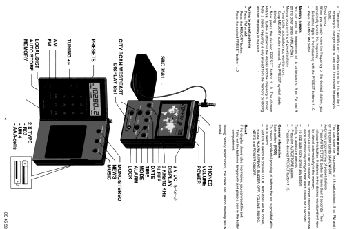
- Shape
- Very small Portable or Pocket-Set (Handheld) < 8 inch.
- Dimensions (WHD)
- 70 x 90 x 27 mm / 2.8 x 3.5 x 1.1 inch
- Notes
- Der KW-Bereich ist durchgehend und per Direkt-QRG-Eingabe möglich (KW 11-120mB). Ausklappbar, LCD-Display mit Weltzeituhr und Weckfunktion.
- Net weight (2.2 lb = 1 kg)
- 0.2 kg / 0 lb 7 oz (0.441 lb)
- Source of data
- Radiokatalog Band 2, Ernst Erb
- Author
- Model page created by Thorsten Brandenburg. See "Data change" for further contributors.
- Other Models
-
Here you find 1077 models, 1011 with images and 856 with schematics for wireless sets etc. In French: TSF for Télégraphie sans fil.
All listed radios etc. from Philips - Österreich
Collections
The model is part of the collections of the following members.
Forum contributions about this model: Philips - Österreich: AE-3905
Threads: 1 | Posts: 4
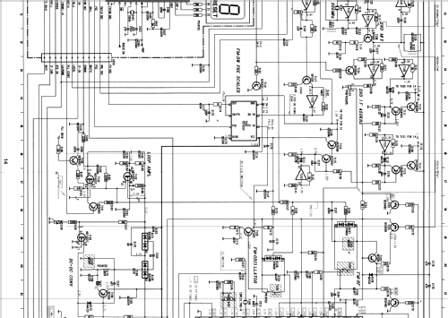
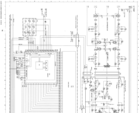
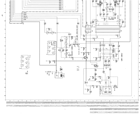
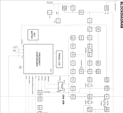
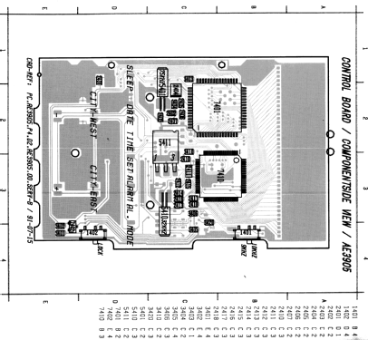
This radio model uses 8 x MM74HCU04M inverter IC's for a total of 48 CMOS gates biased as analog amplifiers. Kind of unorthodox amplification circuits design, don't you think?
Integrated circuits using complementary metal oxide semiconductor (CMOS) gates were designed for binary operation working as two state switching devices in digital circuits, also adequate to work as crystal or RC oscillators and Schmitt Triggers circuits.
However, several unbuffered inverter CMOS gates IC's may also be suitable candidates to work as linear amplifiers, despite the very scarce manufacturers application notes available on the subject.
The MM74HCU04M with its unbuffered single stage inverter gates, with a simplified internal CMOS transistor pairs arrangement, was chosen for this radio circuit to be used as a stable, low to mid gain analog amplifier in several RF and even on AF stages, due to its high noise immunity, high speed, low input capacitance, high input impedance, high fan-out capacity, and transfer characteristics.
This approach requires a clever design to handle potential instability and unwanted oscillation, maintaining each gate within a very narrow operating point in the so called "linear" region corresponding to the transition zone between the ON and OFF states.
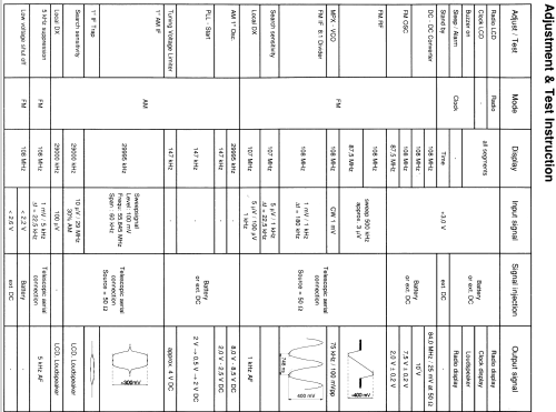
Still, I am surprised to see these gates running at 30MHz (AM RF) and even at 55MHz (1st AM IF) and up to 85.84MHz (1st Local Oscillator). Surely these are selected devices to work in a stable way at that frequencies.
I am not sure about this design choice, considering the alleged (*) inferior sensitivity result when compared with well established designs using JFET transistors as RF amplifiers, for instance.
Still, this is an interesting radio model, unconventional in design, and apparently produced in limited quantities which would make it a collectible model.
(*) Based on some public videos comparing this model against a Sony ICF competitor of the era. Also, my initial tests are not encouraging, with poor MW sensitivity, average FM, and mediane SW, but it may be caused by my unit being defective, as I did not had the time to check it on a lab RF oscillator.
Jose Mesquita, 15.Jun.21