- Land
- Niederlande
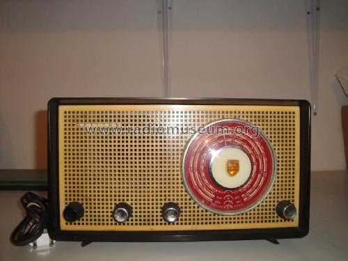
- Hersteller / Marke
- Philips; Eindhoven (tubes international!); Miniwatt
- Jahr
- 1958/1959
- Kategorie
- Rundfunkempfänger (Radio - oder Tuner nach WW2)
- Radiomuseum.org ID
- 75954


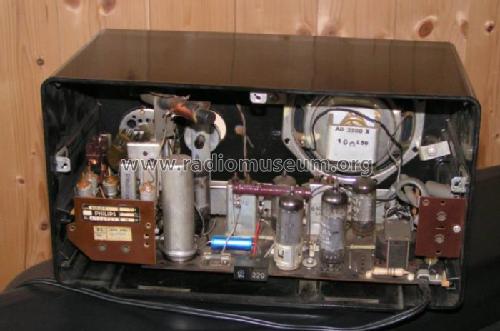
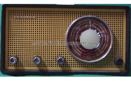
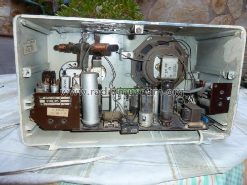
Innenansicht
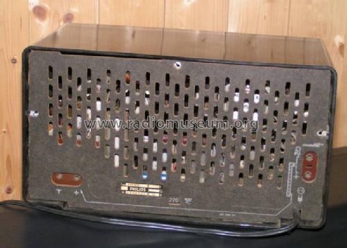
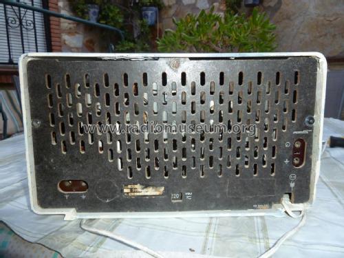
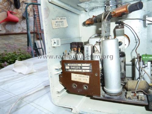
Rückwand

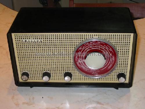
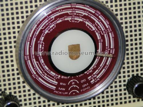
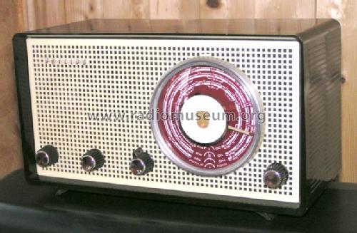
Skalenansichtt
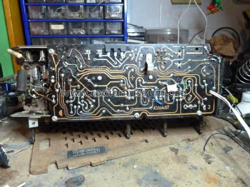
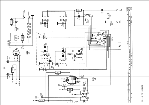
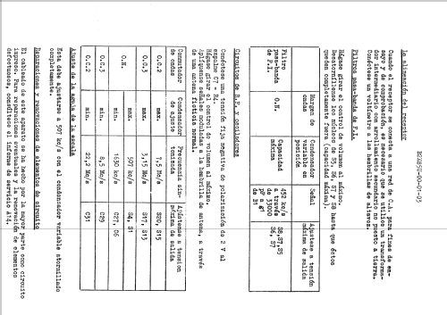
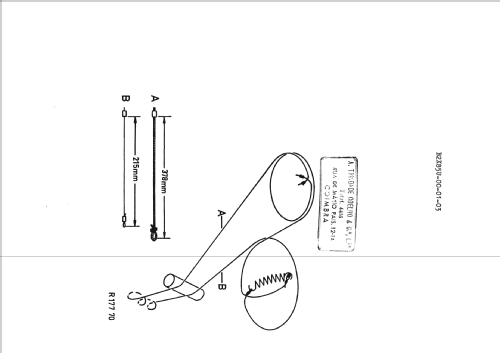
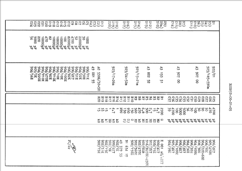
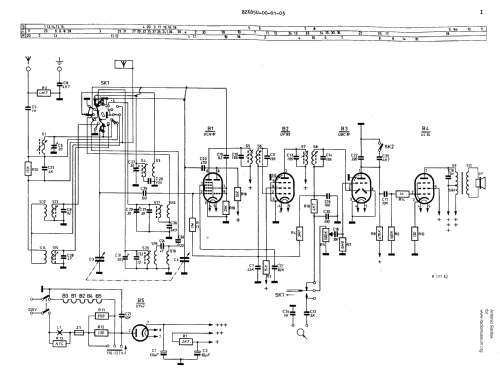
Klicken Sie auf den Schaltplanausschnitt, um diesen kostenlos als Dokument anzufordern.
- Anzahl Röhren
- 5
- Hauptprinzip
- Superhet allgemein; ZF/IF 452 kHz
- Wellenbereiche
- Mittelwelle und 2 x Kurzwellen.
- Betriebsart / Volt
- Allstromgerät / 110, 127, 220 Volt
- Lautsprecher
- Dynamischer LS, keine Erregerspule (permanentdynamisch)
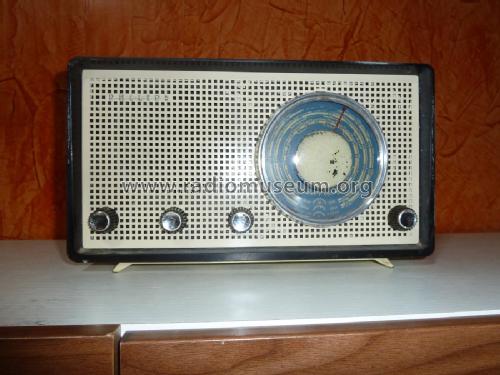
- Material
- Bakelit (Pressstoff)
- von Radiomuseum.org
- Modell: B2X85U - Philips; Eindhoven tubes
- Form
- Tischmodell, Zusatz nicht bekannt - allgemein.
- Abmessungen (BHT)
- 316 x 180 x 150 mm / 12.4 x 7.1 x 5.9 inch
- Bemerkung
- Dial lamp: 8009D (6,3V/0,25A)
- Autor
- Modellseite von Petros Tsirvoulis angelegt. Siehe bei "Änderungsvorschlag" für weitere Mitarbeit.
- Weitere Modelle
-
Hier finden Sie 5279 Modelle, davon 4427 mit Bildern und 3461 mit Schaltbildern.
Alle gelisteten Radios usw. von Philips; Eindhoven (tubes international!); Miniwatt
Sammlungen
Das Modell befindet sich in den Sammlungen folgender Mitglieder.
Forumsbeiträge zum Modell: Philips; Eindhoven: B2X85U
Threads: 1 | Posts: 4
I am restoring a radio Philips B2X85U (or B2K85U). I've got the schematics but I can not realize where to connect the 2 new capacitors in the place of the original can.
I mean, I have 2 capacitors with 4 leads and the PCB of the radio has 5 connection points on the original can.
I guess that the 2 negatives leads have a rail for both of them. Still, I have 4 connection for the other two positive leads.
There is a divider resistor that can solve one lead in two connections but the other positive lead will have to go to the other two connection points?
The pictures will show it.
What I need to know is where I can solder the 4 new leads?
Thanks,
Alvaro Georg
YouTube: Rádios Antigos & Cia Ltda
Brazil
Anlagen
Alvaro Georg, 11.Jan.21