- Pays
- Pays-Bas
- Fabricant / Marque
- Philips; Eindhoven (tubes international!); Miniwatt
- Année
- 1958/1959
- Catégorie
- Radio - ou tuner d'après la guerre 1939-45
- Radiomuseum.org ID
- 75954


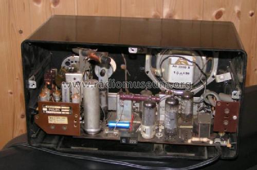
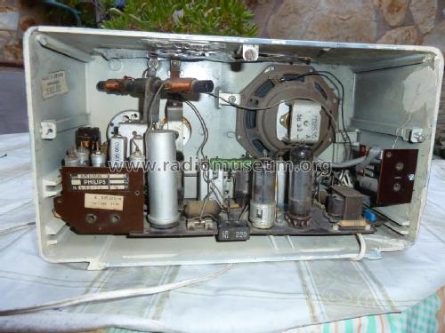
Innenansicht
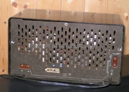
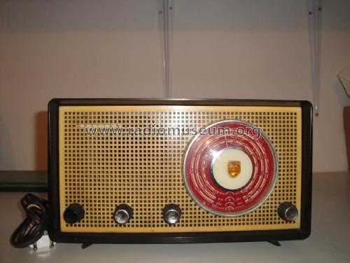
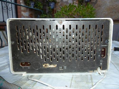
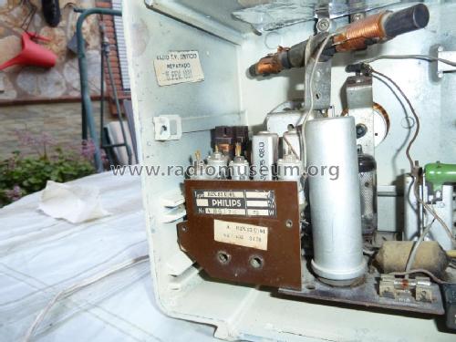
Rückwand

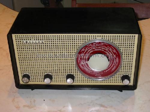
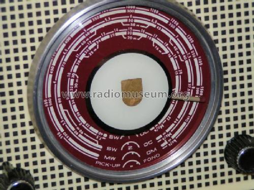
Skalenansichtt
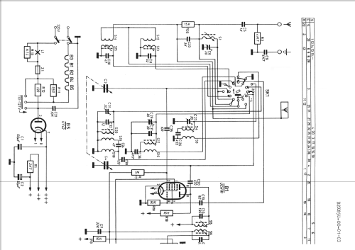
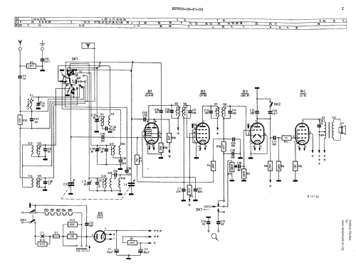
Cliquez sur la vignette du schéma pour le demander en tant que document gratuit.
- No. de tubes
- 5
- Principe général
- Super hétérodyne (en général); FI/IF 452 kHz
- Gammes d'ondes
- PO et 2 x OC
- Tension / type courant
- Appareil tous courants (CA / CC) / 110, 127, 220 Volt
- Haut-parleur
- HP dynamique à aimant permanent + bobine mobile
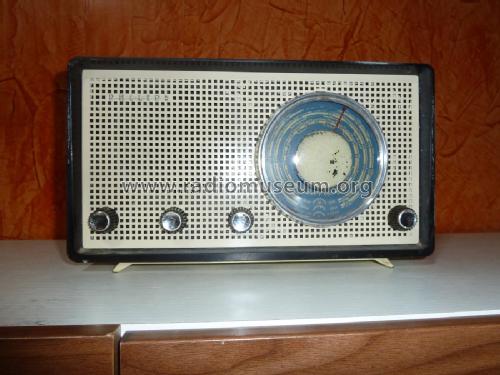
- Matière
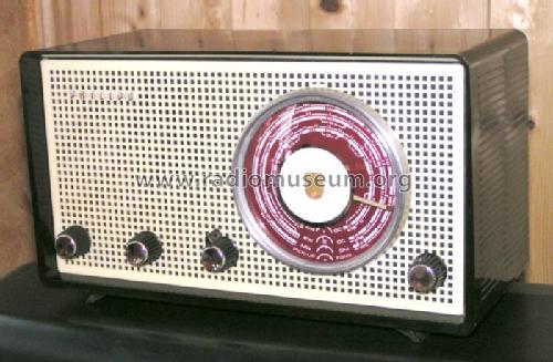
- Boitier en bakélite
- De Radiomuseum.org
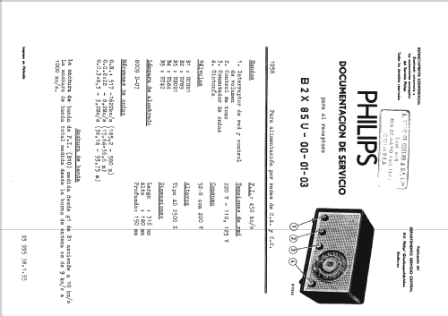
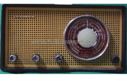
- Modèle: B2X85U - Philips; Eindhoven tubes
- Forme
- Modèle de table générique
- Dimensions (LHP)
- 316 x 180 x 150 mm / 12.4 x 7.1 x 5.9 inch
- Remarques
- Dial lamp: 8009D (6,3V/0,25A)
- Auteur
- Modèle crée par Petros Tsirvoulis. Voir les propositions de modification pour les contributeurs supplémentaires.
- D'autres Modèles
-
Vous pourrez trouver sous ce lien 5279 modèles d'appareils, 4427 avec des images et 3461 avec des schémas.
Tous les appareils de Philips; Eindhoven (tubes international!); Miniwatt
Collections
Le modèle fait partie des collections des membres suivants.
Contributions du forum pour ce modèle: Philips; Eindhoven: B2X85U
Discussions: 1 | Publications: 4
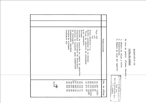
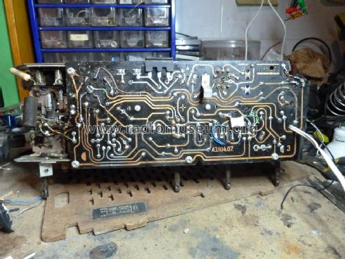
I am restoring a radio Philips B2X85U (or B2K85U). I've got the schematics but I can not realize where to connect the 2 new capacitors in the place of the original can.
I mean, I have 2 capacitors with 4 leads and the PCB of the radio has 5 connection points on the original can.
I guess that the 2 negatives leads have a rail for both of them. Still, I have 4 connection for the other two positive leads.
There is a divider resistor that can solve one lead in two connections but the other positive lead will have to go to the other two connection points?
The pictures will show it.
What I need to know is where I can solder the 4 new leads?
Thanks,
Alvaro Georg
YouTube: Rádios Antigos & Cia Ltda
Brazil
Pièces jointes
Alvaro Georg, 11.Jan.21